This tutorial is based on the really useful GitHub pages on the Tuya-Convert Github repo. These notes are an abbreviated form to help connect to the CE-Lab infrastructure. This Youtube video was also helpful to see how others had done the flashing.
To complete this task you will need:
- Tuya compatible plugs such as these Gosund UP111 Smart Plugs
- Raspberry Pi to flash the firmware
- MQTT broker running
Build a standard vanilla RPi and connect it to your wifi network.
Do the usual updates:
sudo apt update
sudo apt upgrade -y
Install Git, get the tuya code and install it:
sudo apt install git
git clone https://github.com/ct-Open-Source/tuya-convert.git
cd tuya-convert
sudo ./install_prereq.sh
Your RPi is now set-up and ready to flash Tuya Plugs.
The process of flashing a plug is:
- log into RPi and run a flashing script
- plug in a device to be updated
So to get started make sure you are logged into RPi and move into the tuya-convert directory. And grab a plug to flash.
cd tuya-convert
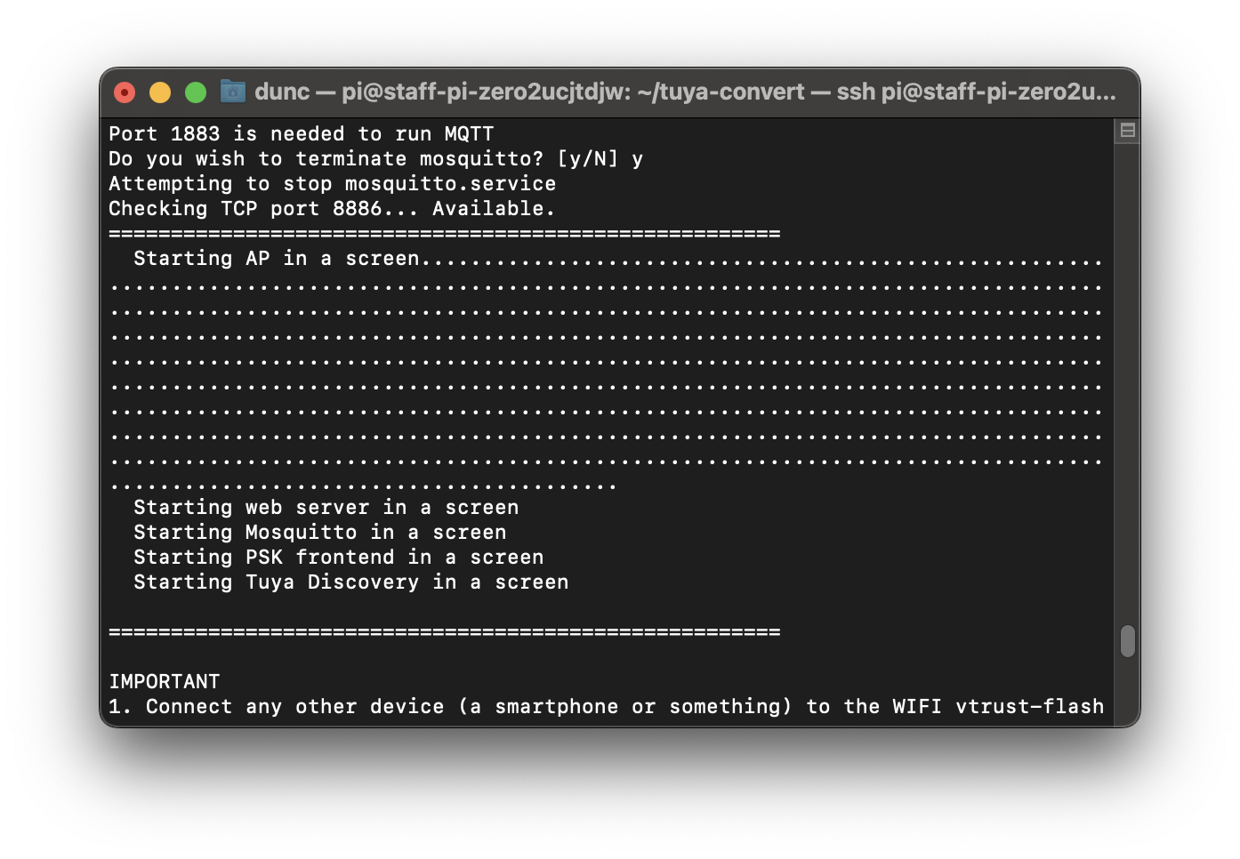
sudo ./start_flash.sh
Select ‘y' for all the prompts until you get to the prompt : "Starting AP in a screen"
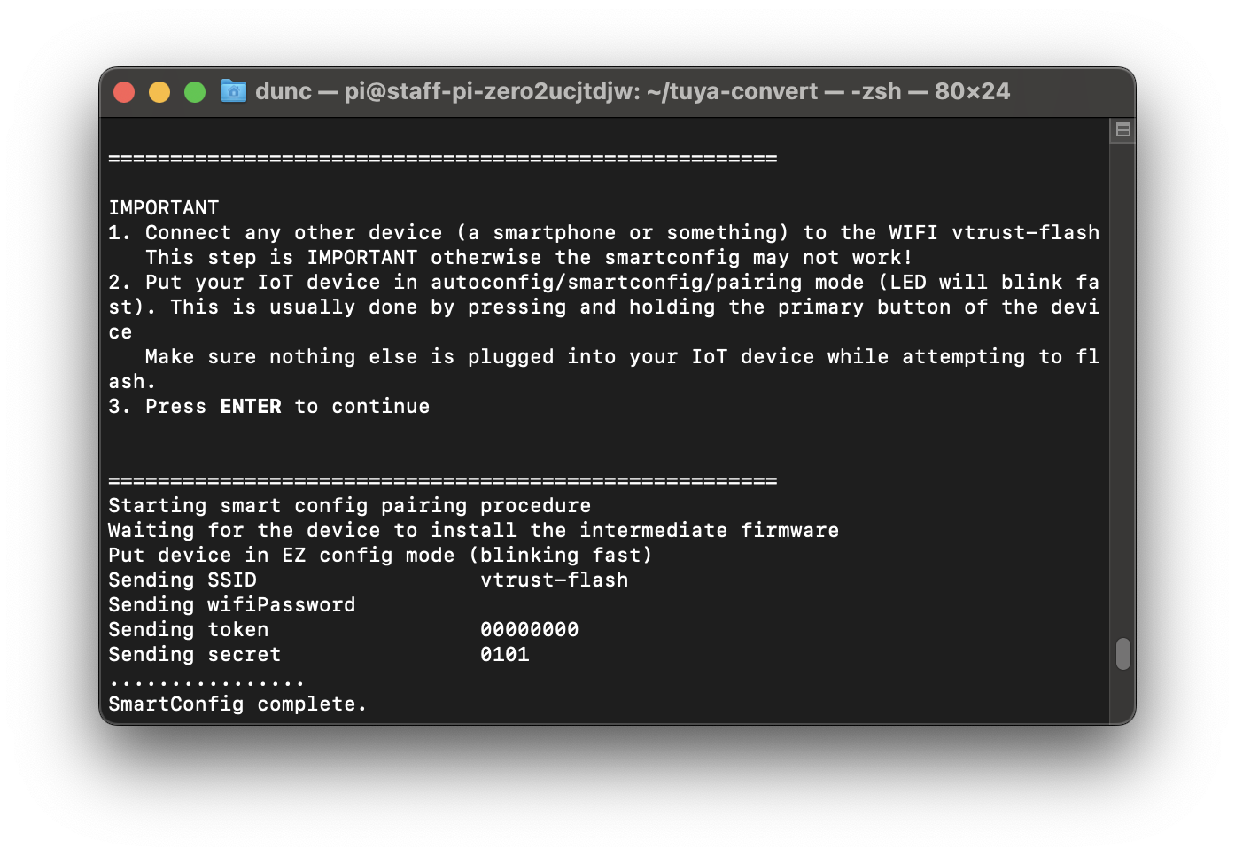
Once connected to the VTrust network you should see a screen similar to:
From here you should see a prompt to plug in a device for flashing (item 2 in the list) - plug in your device - if it is out the box it should already be in "config" mode - ie flashing.
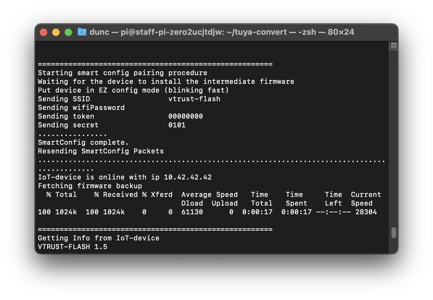
After a while you should see the plug appear and flashing start - be a little patient here - this can take a few minutes.
Eventually you will see the option to flash Espurna - select that.
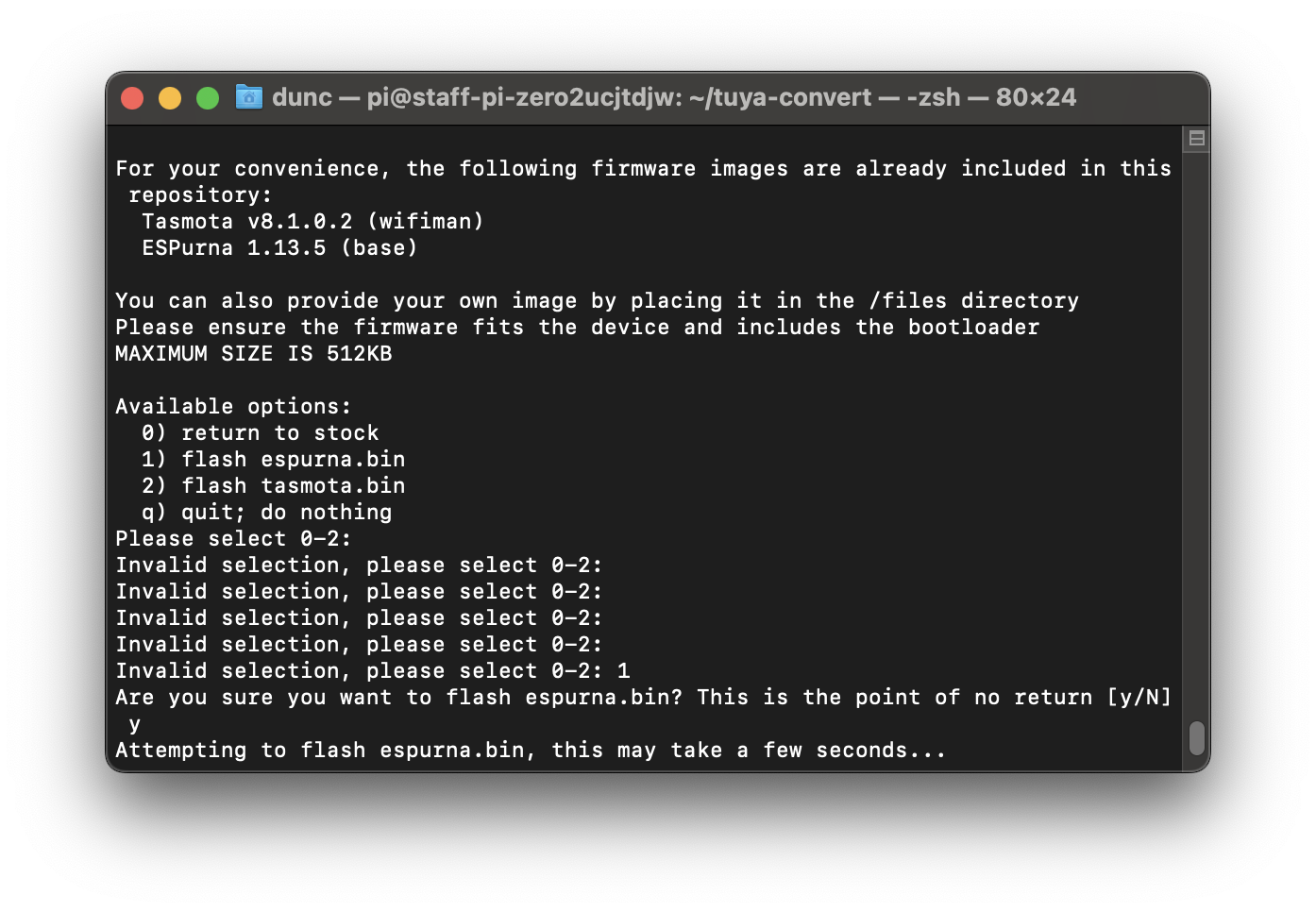
Finally you will see a flashing complete message such as below.
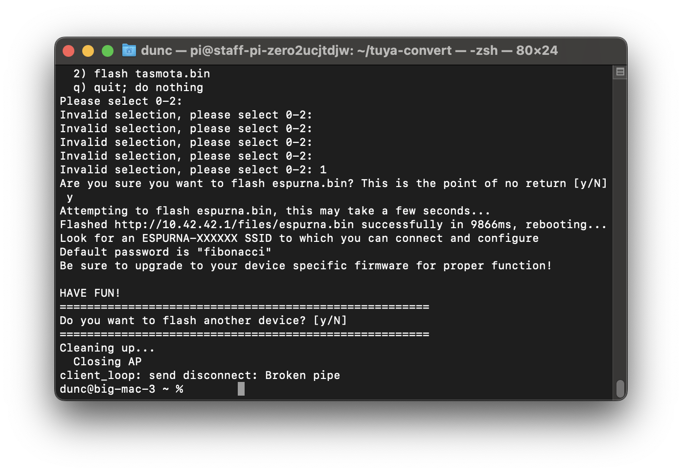
The plug should now be flashed and ready for configuration.
At the time of creating these instructions there was no Espurna configuration for the Gosund UP111 plugs (Espurna v 1.14.1). Was not sure if SP111 was valid replacement but this was still only on Dev release (v1.14.2) - Espurna wiki.
Tasmota was therefore chosen for the MQTT integration.
After flashing device it will restart in AP mode - in our wifi network settings you should see a device with Tasmota_XXXXX name. Connect to that network, a capture portal will start, complete the setup of the wifi connection to your local network.
Once restarted browse to your routing settings to find the IP address of the device. You should see a page similar to below.
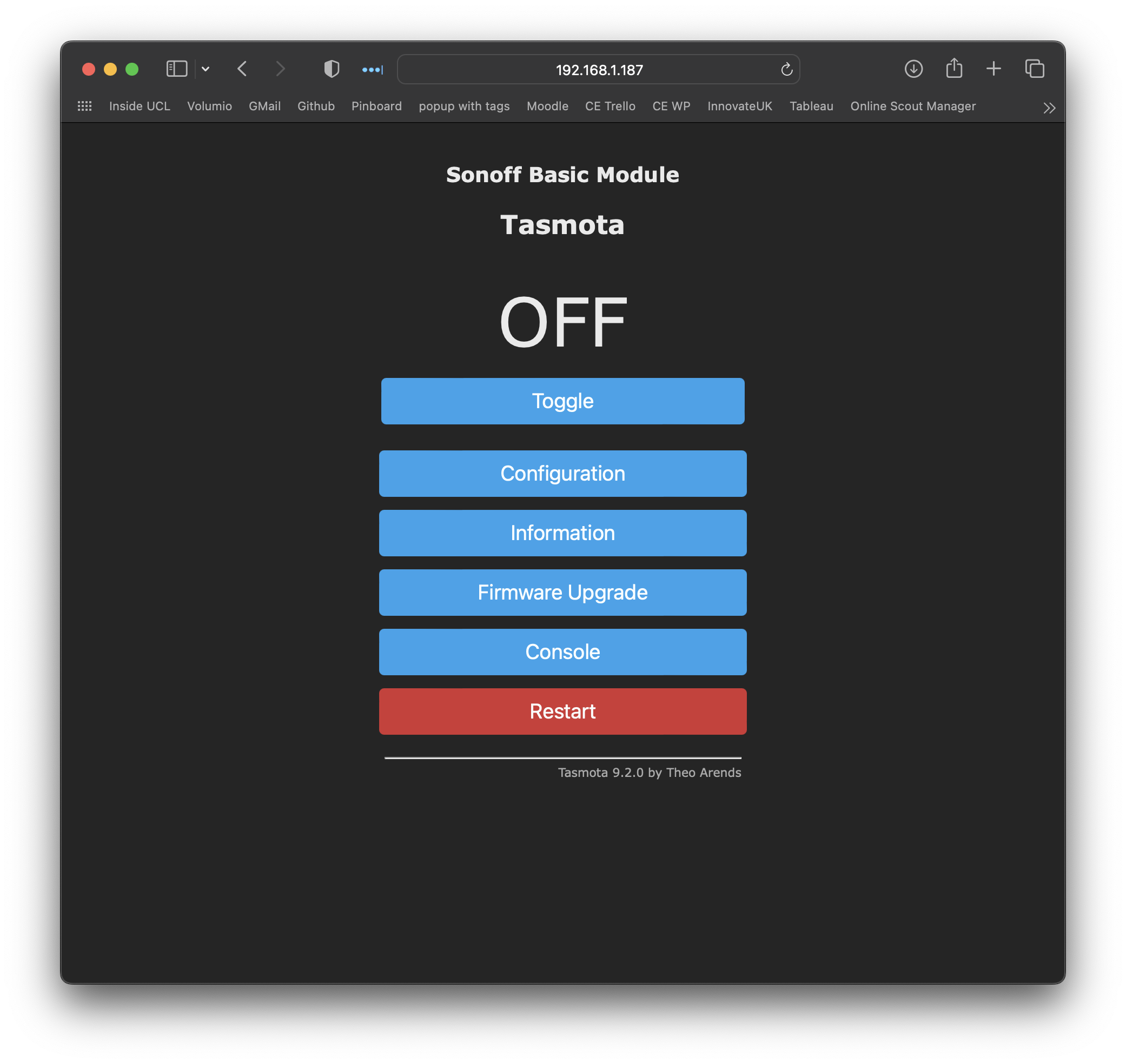
Click on Configuration and then Configuration Other and enter the following template:
{"NAME":"Gosund UP111","GPIO":[0,320,0,32,2720,2656,0,0,2624,576,224,0,0,0],"FLAG":0,"BASE":18}
And give a name to your device as per below example:
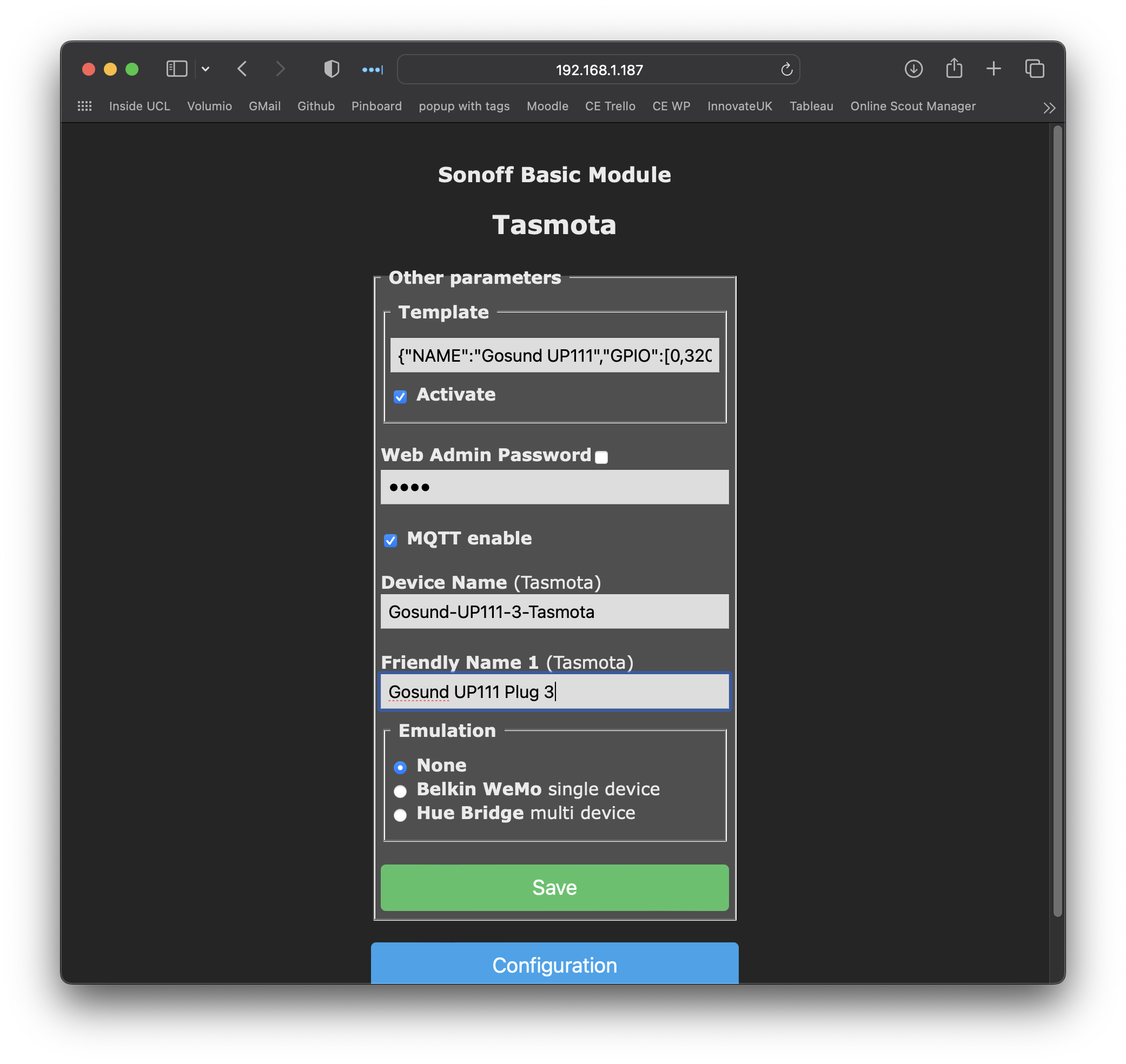
The device will then restart.
Next we will run an upgrade on Tasmota to get to the latest version. From home page select Firmware Upgrade and then select automatic upgrade.
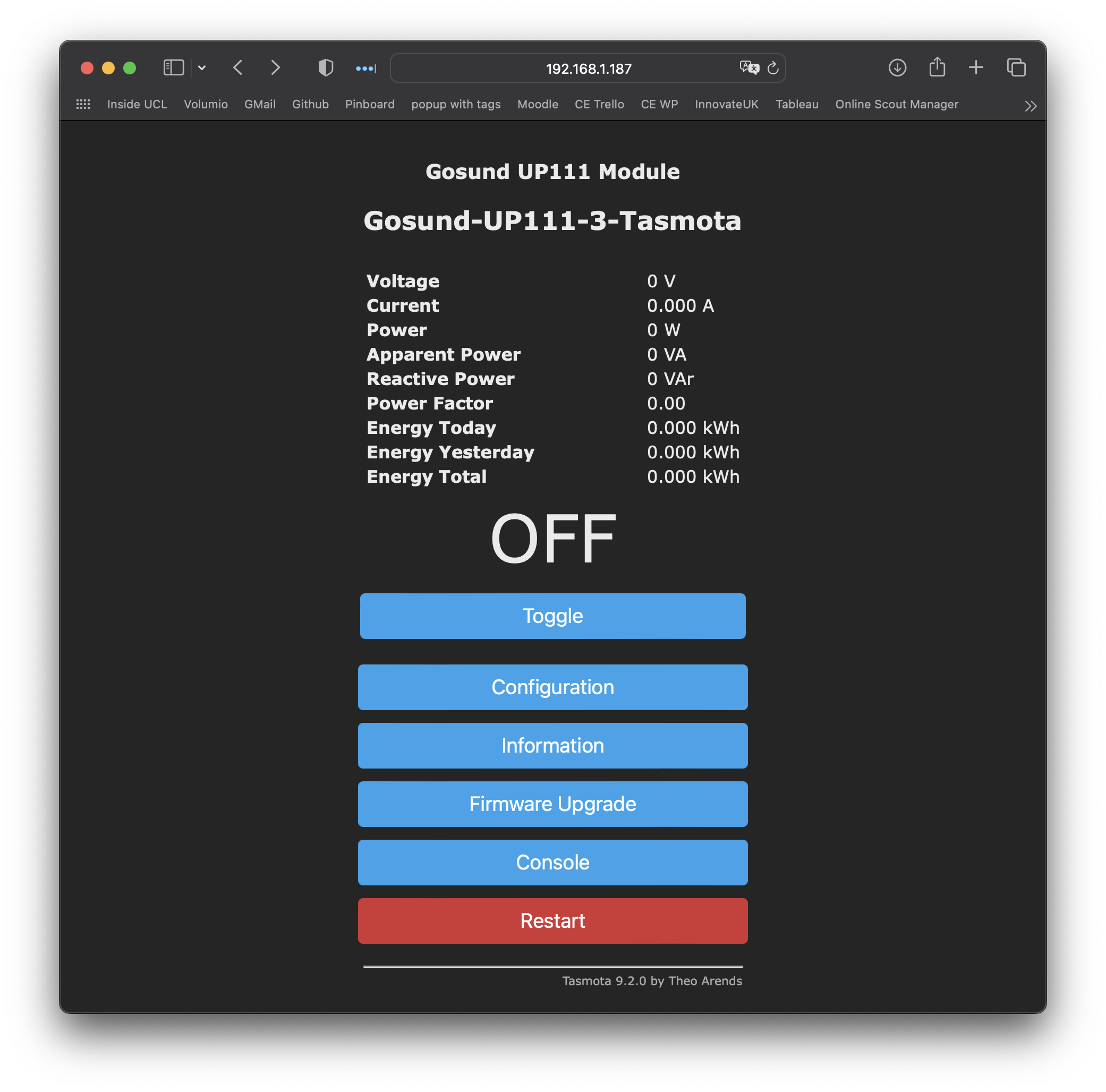
Once upgraded and restarted we will configure MQTT.
Next up configure the MQTT settings with the following (note: leave all other fields as is).
- broker = mqtt.cetools.org
- port = 1884
- user = CEDevice
- pass = (in LastPass)
- topic = gosund-up111-%n%
- Full Topic = ucl/%building-name%/%zone%/EM/%topic%/
For example:
%building-name% = 90TCR
%zone% = 106
%n% = 3d-printer2-4184AB
so full topic = ucl/90TCR/106/EM/3d-printer2-4184AB

Once restarted click on Configuration and select Configure Logging and change the Telemetry Period to 30 (every 30 seconds). Also select the info to be published alongside the sensor data
Finally we need to activate the MQTT feed. Go back to home page and select Console. Where it says Enter Command paste in the following command:
SetOption19 on
Data should now be flowing into MQT broker.
All done.
For more info on settings view the commands section of the GitHub and Tasmota Supported Devices Repository ( UP111 example )