This workshop will show you how to
- Design and build a Data Device in Autodesk Fusion 360
- Import digital models into Fusion 360
- Create Technical Drawings
- Export - Ready for Blender/SketchFab/Unity
It takes approximately 3.5 hours from start to finish (it should be enjoyable though) - it covers almost everything you need to know in Fusion 360 - in the workshop we will aim to go through the first part of the build. Other parts should be completed before the Blender/Augmented Reality Lecture on Thursday as you will be using the model you build in this workshop.
Enjoy.
As a core part of this module we released Open Gauges - providing full access to the graphics files, code, 3D printing resources to make any number of data driven physical and digital Gauges. After this workshop, and the course work, we look forward to you contributing and being part of the Open Gauges project.
To complete this workshop you will need the following:
Software
Hardware
- Node MCU - Provided
- or Pi Pico W
- MG90s Servo - Provided
- NeoPixel Ws2812B 144LED Strip - Provided
- Perspex or Laser Cut your own - Pool Street Workshop
- Magnets x 3 - Provided - only for Optional Version
- 3D Printer - Prusa MK3S+
- Arduino Sketch from GitHub - On GitHub - Editable for any MQTT feed
- or Micropython from GitHub - On GitHub - Editable for any MQTT feed
Texture and Resources
A complete working version in Fusion 360 format, all textures, etc can be found on the Open Gauges GitHub page - but don't download it yet, follow the tutorial and learn how to make your own...
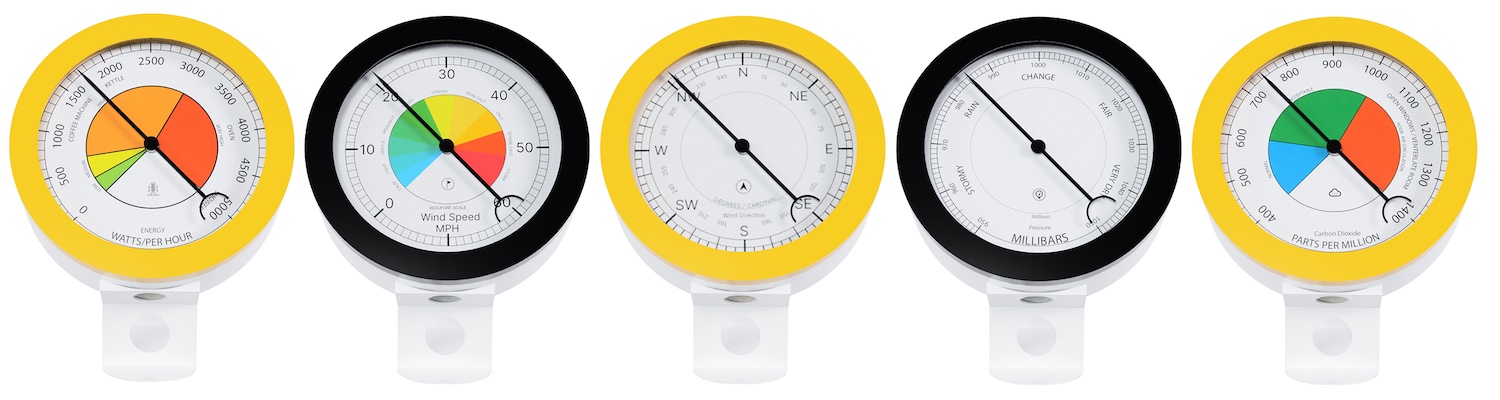
- Wind Speed MPH / Beaufort Scale Texture - The Open Gauges Github provides 5 different dials (tbh I like Wind Direction the best but pick any and then make your own in Figma or Illustrator). See the Graphics folder.
- Fusion 360 Manual and Documentation
Human
Concentration, Attention to the Details, Patience & Coffee/Tea....
The digital object is the basis for everything - the Physical Object becomes the ‘Twin', rather than the common concept of a ‘Digital Twin'. We will use Fusion 360 to design a Gauge/Dial to display real-time data. This can be from any feed and from any location. It is made to hang on a wall, taking a nod from traditional designs (we discuss more in the Enclosure Lecture) or sit on a desk in physical form.
In digital form it forms the basis for displaying data in both Augmented Reality and Virtual Worlds - completing the circle between the digital and physical device, both linked to real-time data.
Key Requirements
- Ability to display near real-time data (an update every 3 seconds)
- Adaptable to Multiple Data Feeds
- Have a range of 360 degrees
Multiple Parts
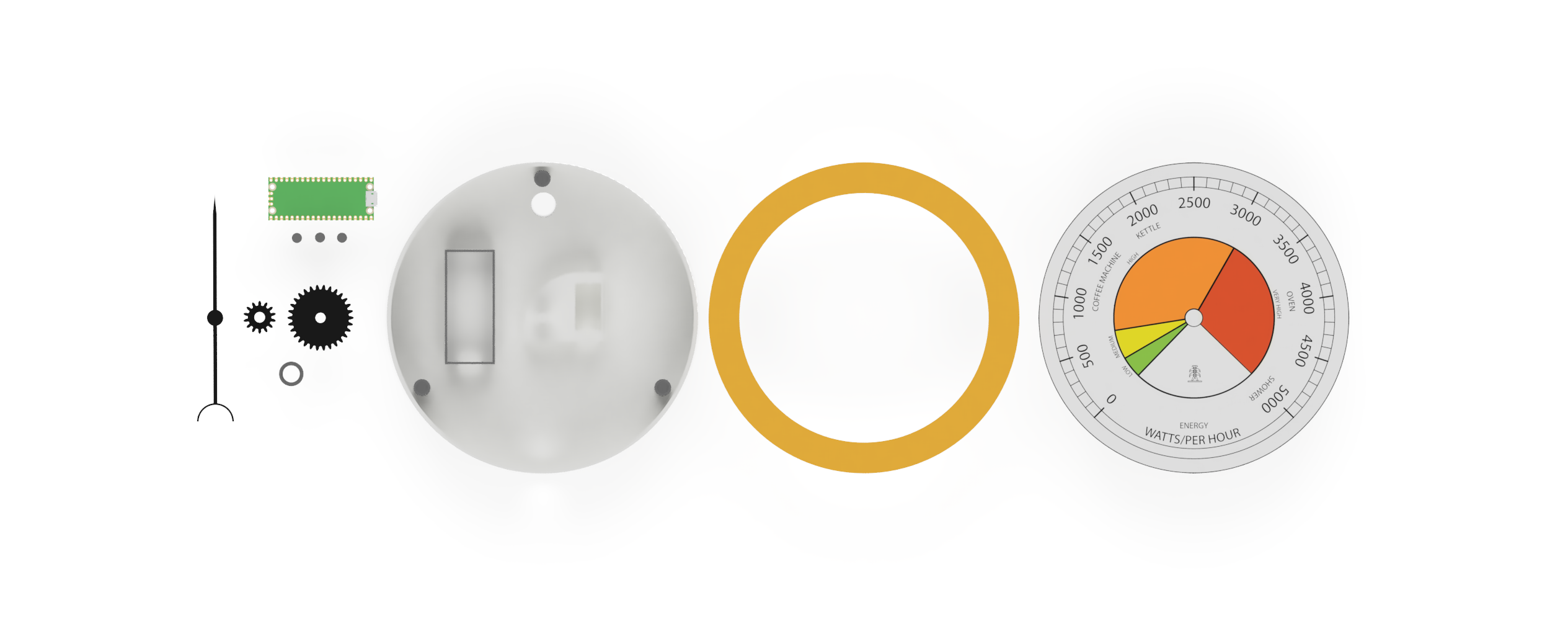
- Node MCU /Pi Pico W Holder
- Needle/Pointer
- Base and holder for the main components
- Dial Holder
- Dial (via Figma and Inkscape)
- Perspex Holder
- Gear Train to adapt a 180° degree servo to 360°
- LED Lights to ‘Light' and show additional data
- Screw Top / Magnetic Top
The Servo Holder and Gear Train are arguably the main part of the data gauge. Our Servo - the MG90s - was selected due to both its low cost and ability to know its last position, making it relatively easy to map data feeds to movement.

Other options include a Stepper Motor - these negate the need for a Gear Train but require ‘zeroing' on every start up and can run hot when used for long periods of time.
In these first steps we will explore the following concepts in Fusion 360:
- Components
- Sketches
- Offset
- Fillet
- Projection on Face
- Press/Pull
- Trim
- Spur Gears
- Importing Mesh
- Move/Rotate
- Capture Position
- Visibility
These are the core skills required and we will reuse them throughout the whole build.
First Steps - A New Component
An object in Fusion360 is made up of multiple components. It provides a structure to the model and allows a complex model to remain navigable.
It is important to always aim for a logical structure in Fusion 360.
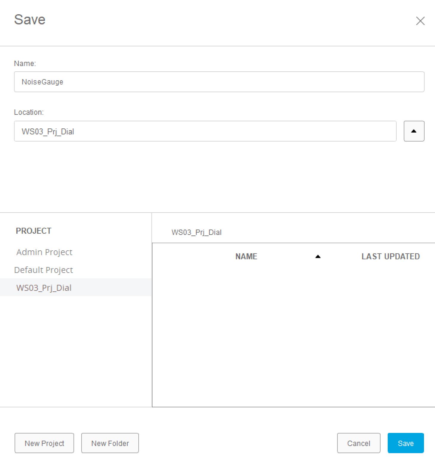
Open Fusion360 and Save your file in the Admin Project Location or in a new Project Folder. Fusion360 stores all the file on your Autodesk account online.
Lets create our first Component using the dropdown menu Create -> New Component
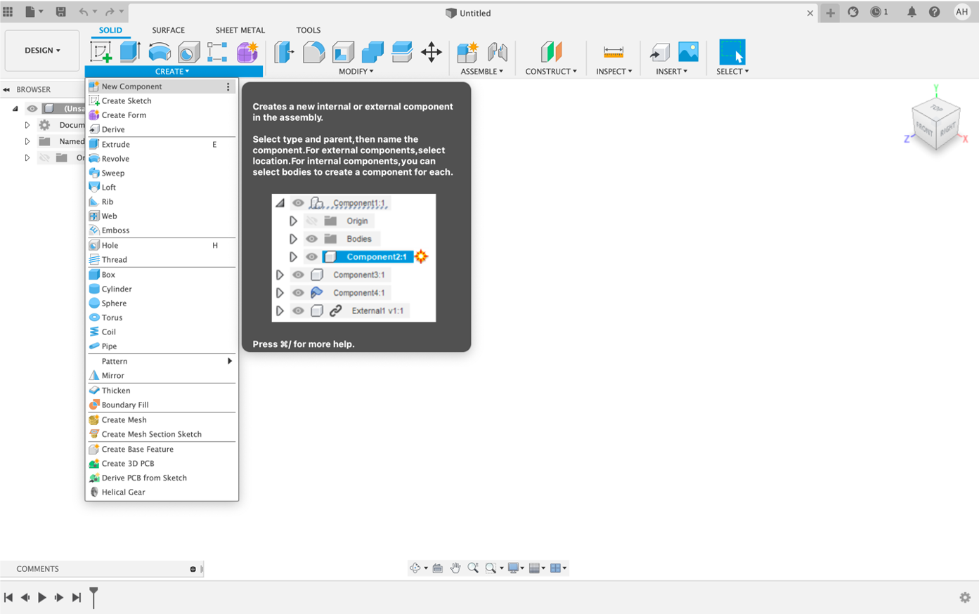
Give your Component a name ServoHolder and Save your file.
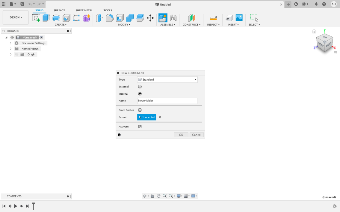
You now have an empty Component ready to be filled with a 3D model.
First Steps - Create a Sketch
Sketches form the basis of Components. You can select a plane of a face on which to draw a sketch , they contain the dimensions and the 2D layout of your Components. You can go back at any point and edit a Sketch to, for example, change a Dimension and the relative Component will automatically update itself.
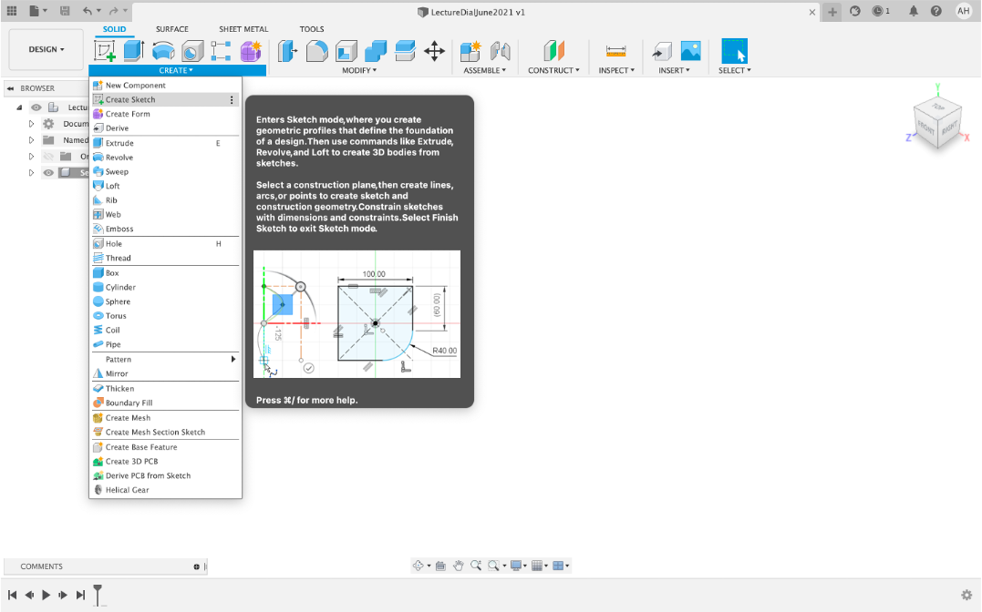
Create Sketch and click on the flat plane to select the surface location. This creates our first empty sketch.
Before we add anything into our first Sketch we need to know the dimensions of our Servo.
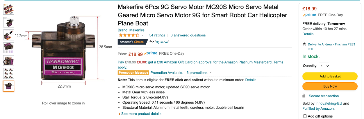
The servo is listed as 22.8 x 12.2 x 18 mm. We are going to make a holder for the servo which simply slots in - this requires a tight fit. A good measure to use for ‘snap in' connectors, lids, components is an additional 0.3 mm to the original size.
This is dependent on the 3D printer, settings and filaments used so it is open to adjustment. A safer method would be to allow for some play in the holder and to fix it using screws. However, where is the satisfaction in that....
First Steps - A Centre Point Rectangle and Dimensions
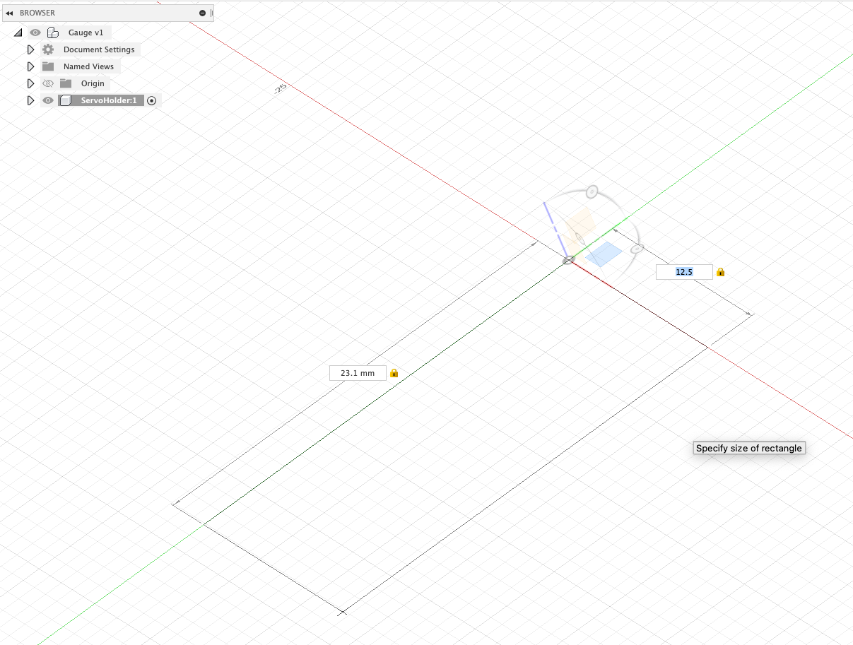
From the dropdown menu Create -> Rectangle -> 2 Point Rectangle
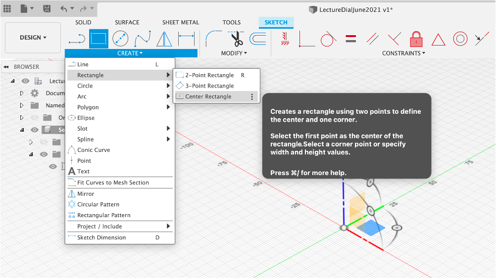
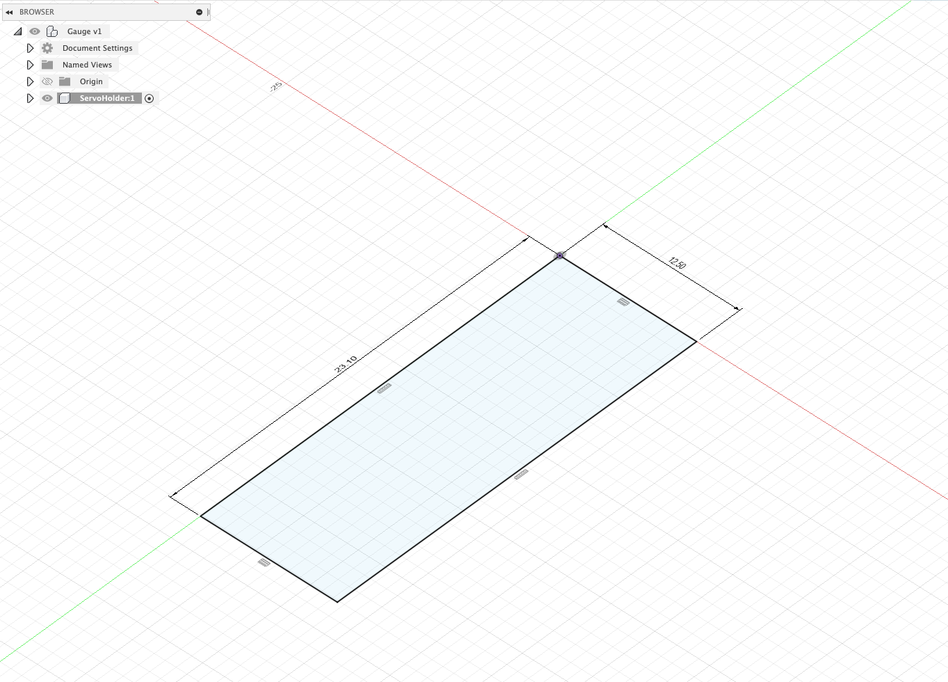
Drag out and enter the dimensions (e.g. 23.1 mm by 12.5 mm) use tab to change edge and press Enter to confirm. Double click on the value of the dimension if you need to edit it.
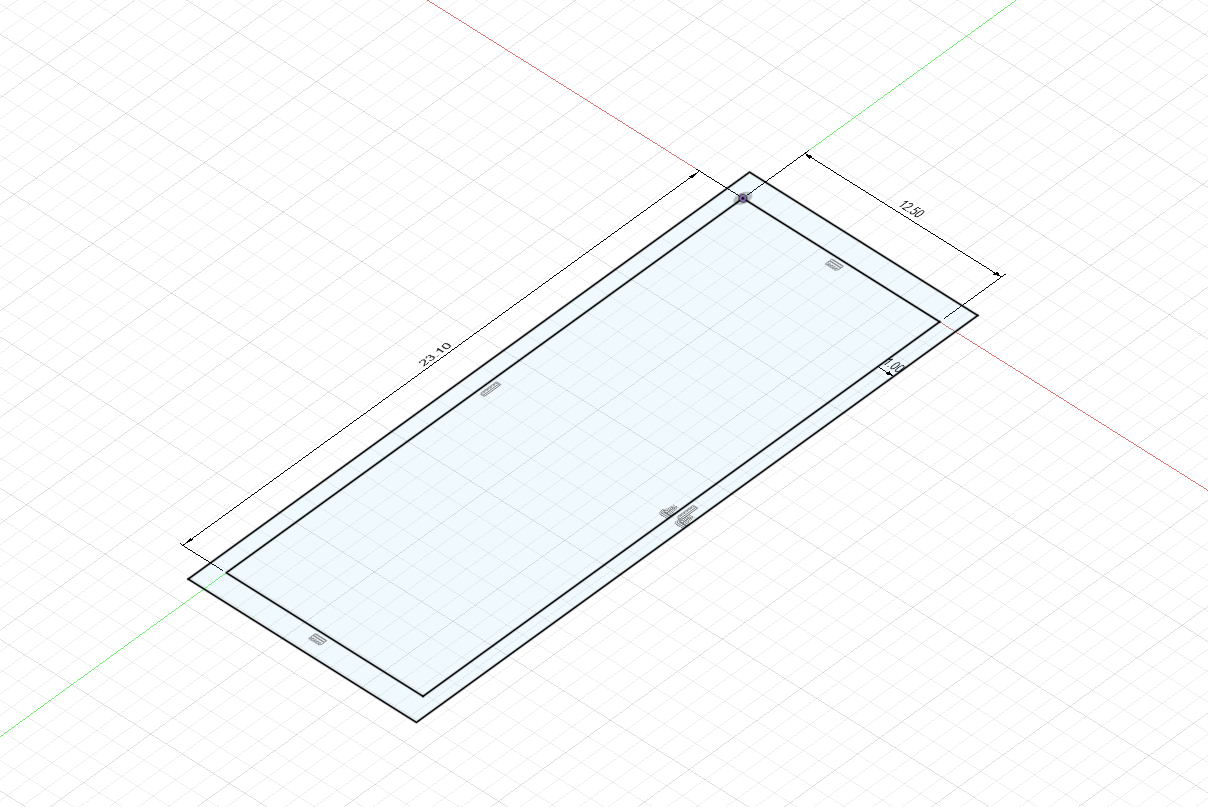
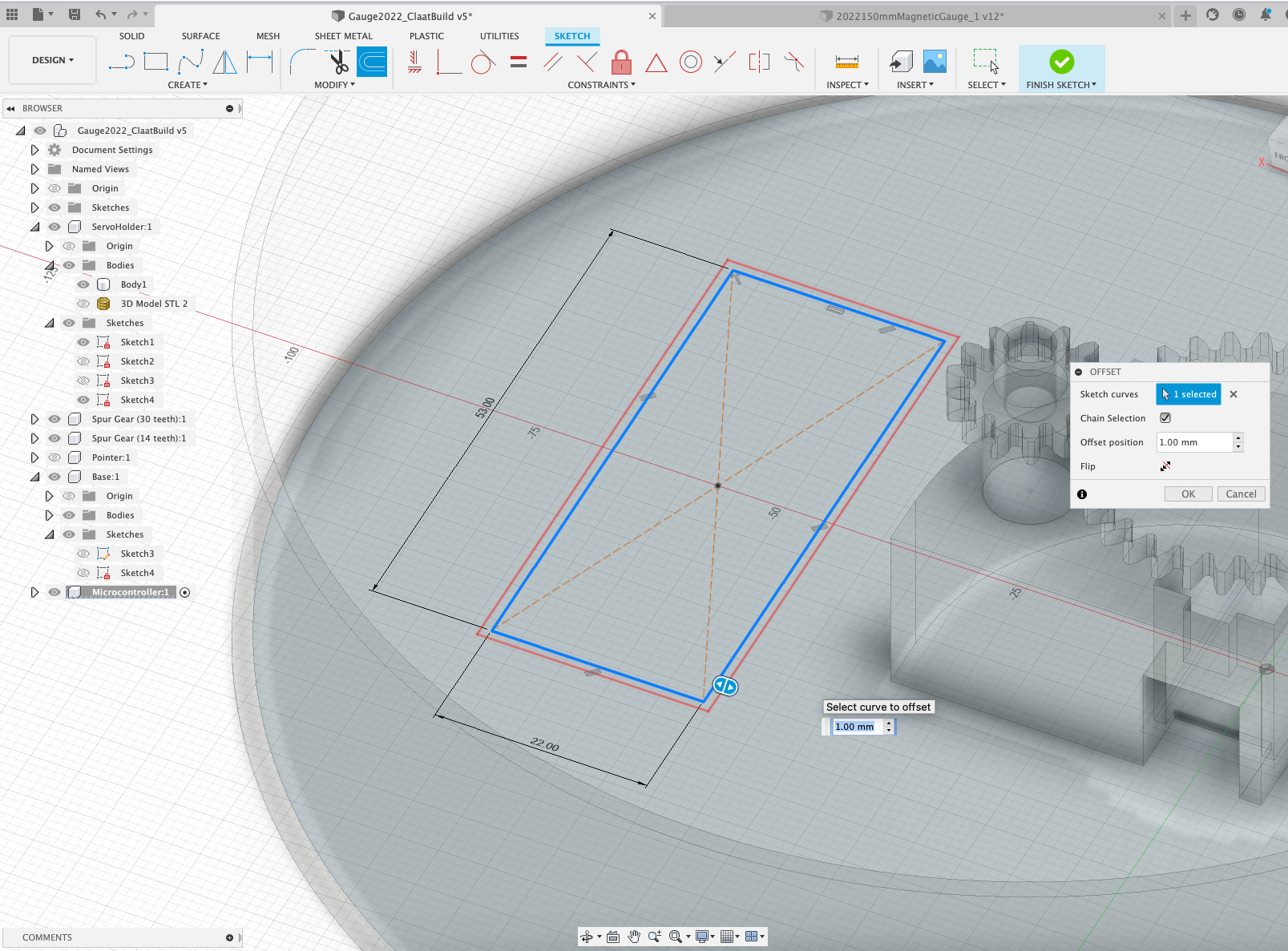
First Steps - Offsets
Offsets are useful to create an offset (obviously!) - i.e. creating a wall around the initial rectangle. Select the border (e.g. double click on one of the border) of the rectangle and press o on the keyboard to shortcut and -pp
The size of the offset is typed in 1mm (i.e. outside the box)
First Steps - Press Pull
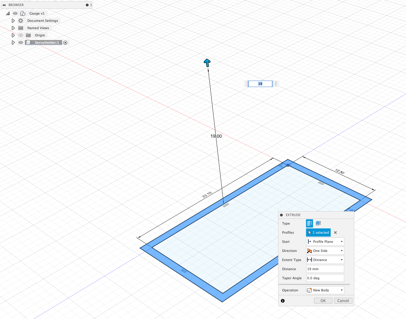
Press Pull allows you to move faces up and down - thus the name Press Pull. Highlight the offset, Modify/Press Pull or Q as a useful keyboard shortcut.
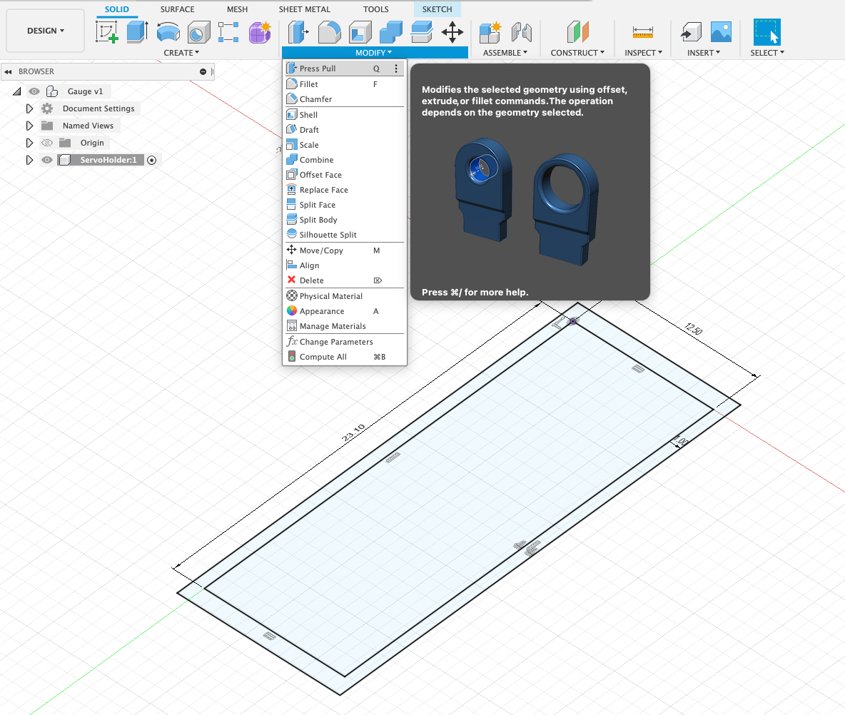
The size typed in 19mm (this is the 18mm height an allowing 1mm for the base of the Gauge). Press ‘OK' to Complete the Press/Pull.
Your component should now look as per:
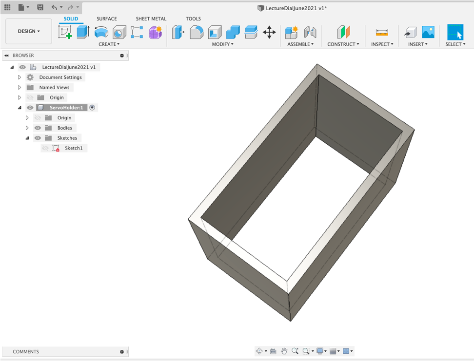
You now need to add the base - note the sketch has disappeared. This is an early quirk to note. Click the eye to reshow the Sketch and Modify/Press Pull or Q1mm.
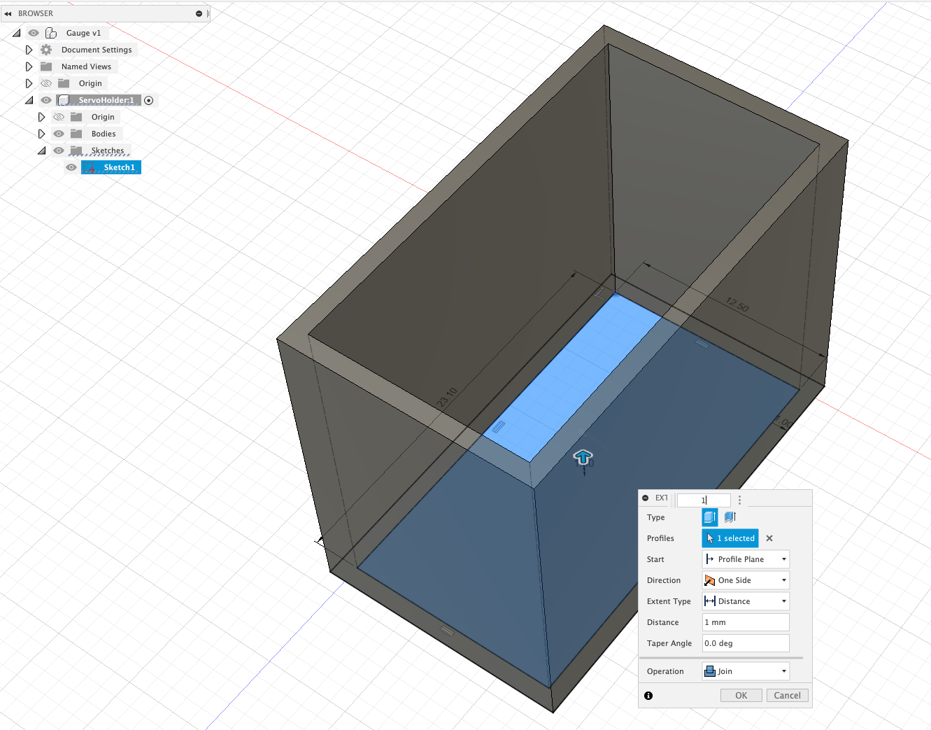
After all that - you have a box - but the box is the start of the ability to make almost anything in Fusion 360.
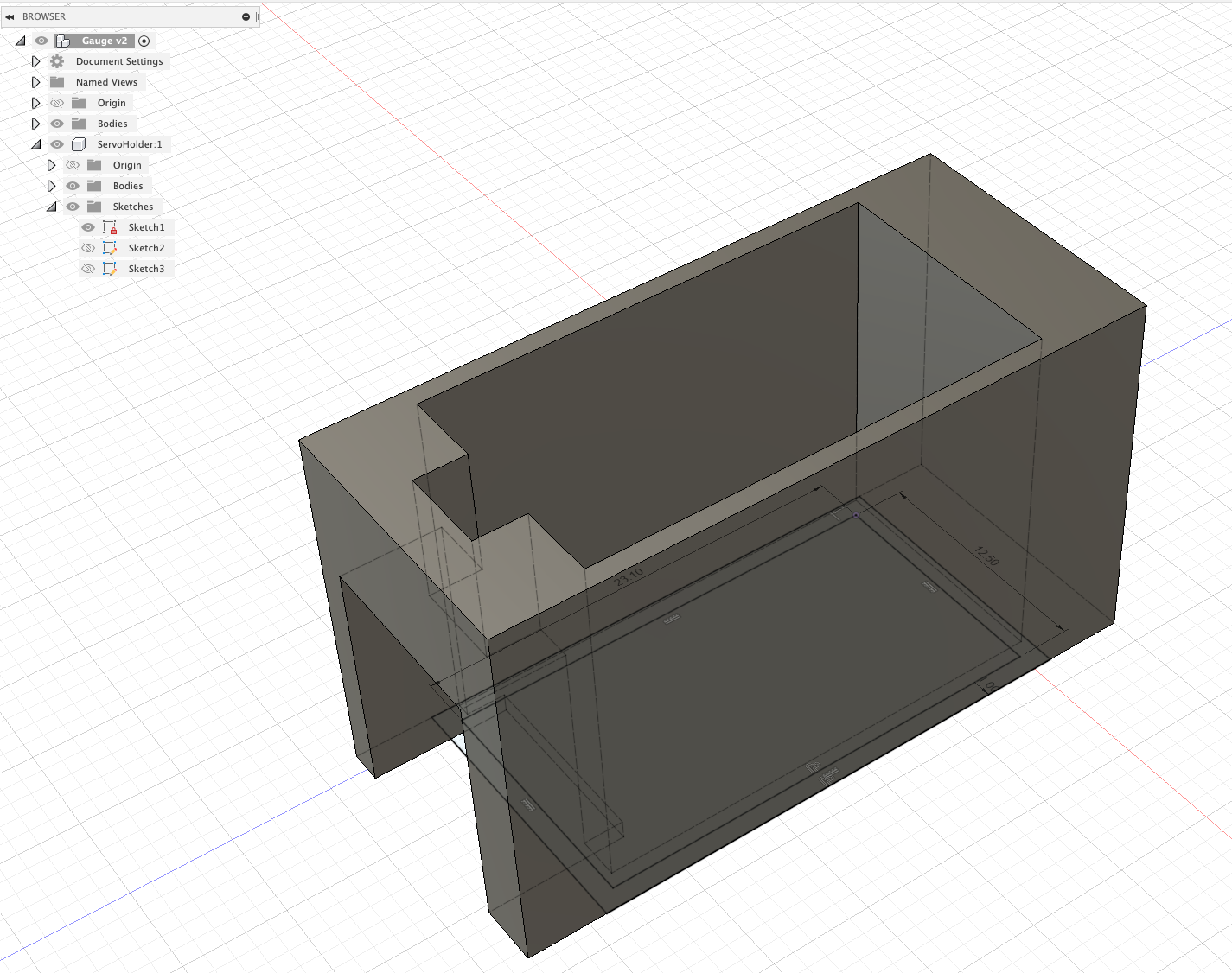
We now want to add the space for the screw tabs - Modify/Press Pull or Q, change Offset Type to New Offset on the end face by 4mm.
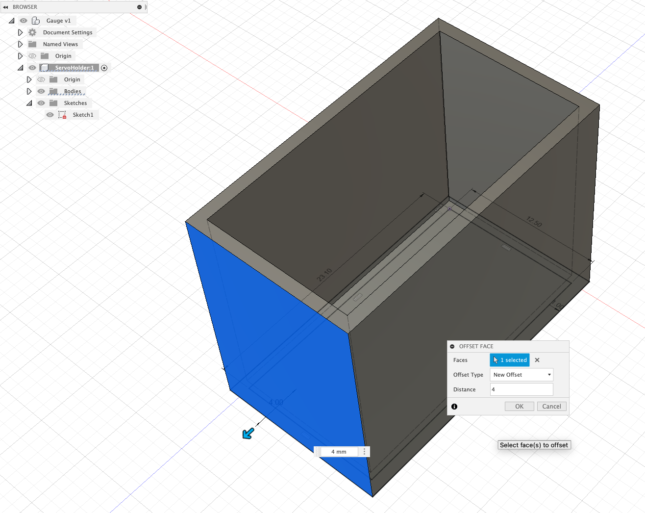
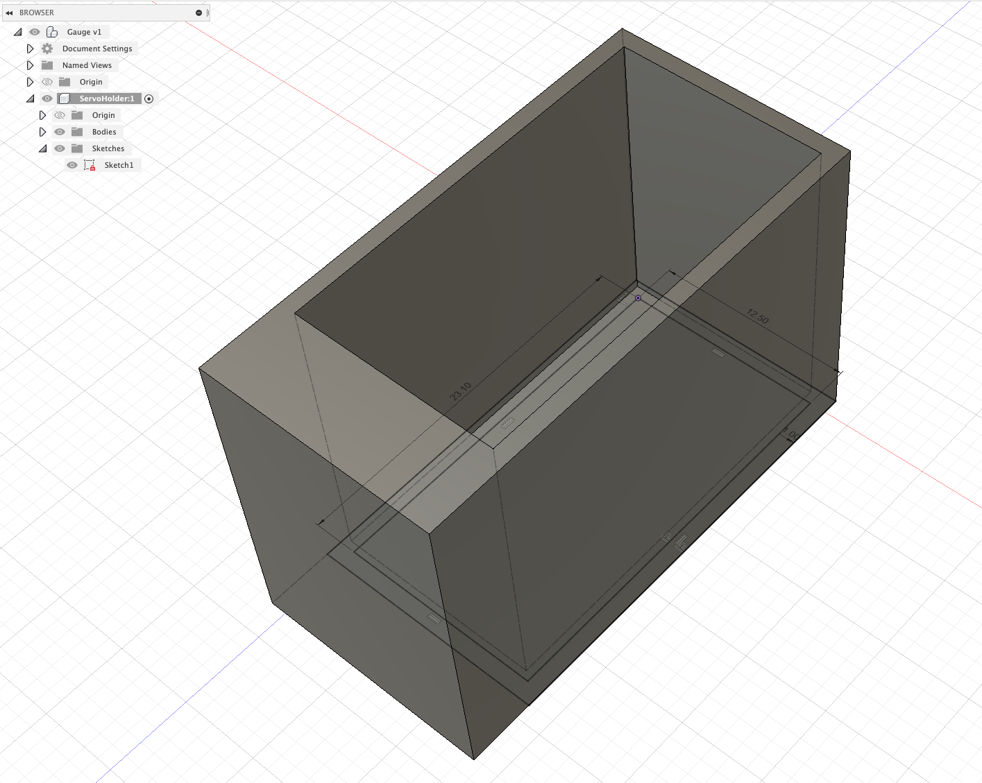
Repeat this for the opposite end - creating a space for the servo to sit.
First Steps - Sketch on Faces
We now need a space for the wire of the servo to feed through.
Sketches can be made on faces - allowing you to form/cut new shapes.
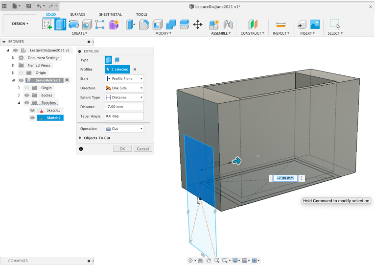
Select the End Face and Create -> New Sketch
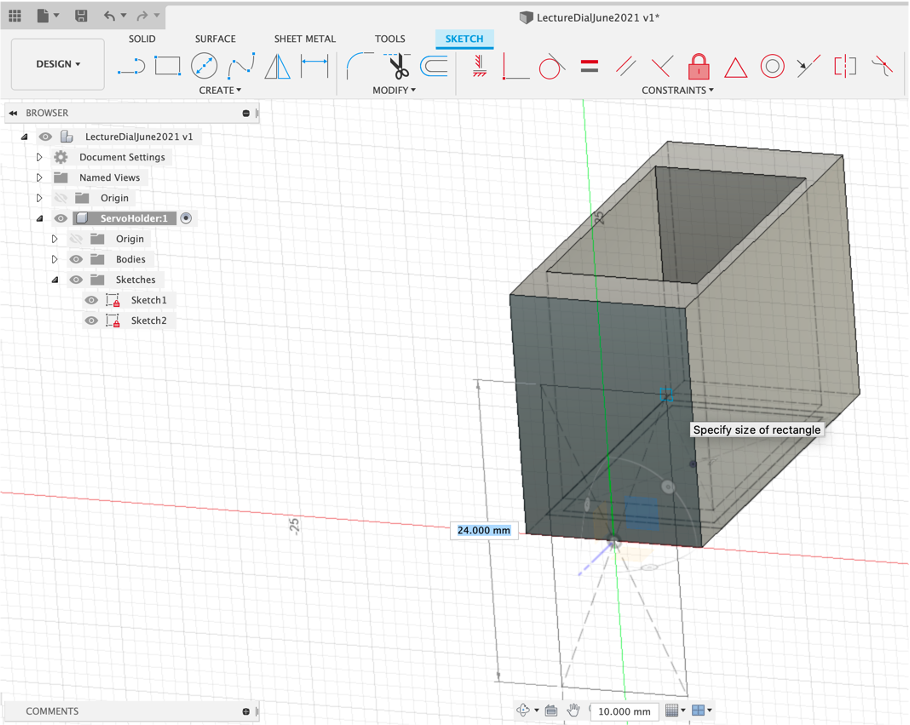
Add a Create -> Rectangle -> Centre Point Rectangle of 24 mm by 10 mm, select the top part and again Press Pull, or Q, -7mm and Cut (press OK to confirm or press Enter)
As our size constraints are only 0.3mm the servo will need to be slotted in directly into the slot. Although we have used the Servo dimensions they do not take into account the protruding wire coming out the front. As such we also need to make a slot to allow us to slide in both the servo and the wire.
Select the Top Face and Create -> New Sketch
Add a Create -> Rectangle -> Centre Point Rectangle of 4.8 mm by 3.5mm (use ‘Tab' to switch between dimensions).
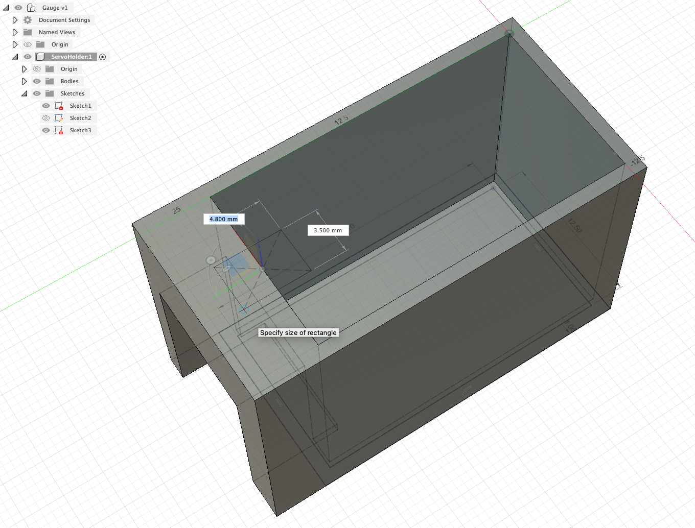
Press Pull (Q) until it creates a hole down through the top and Cut
Well done - you have a basic (and a little ugly) Servo Holder.
As with other 3D modelling platforms Fusion 360 allows the ability to import objects. This can be useful to add new components to you scene and to add reference models.
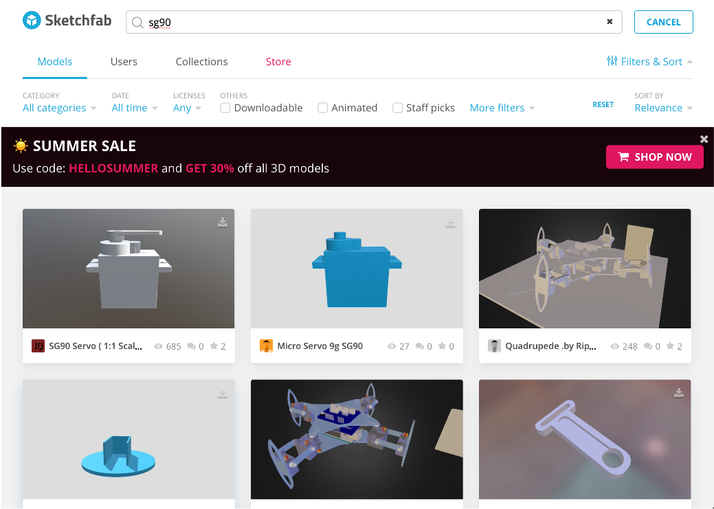
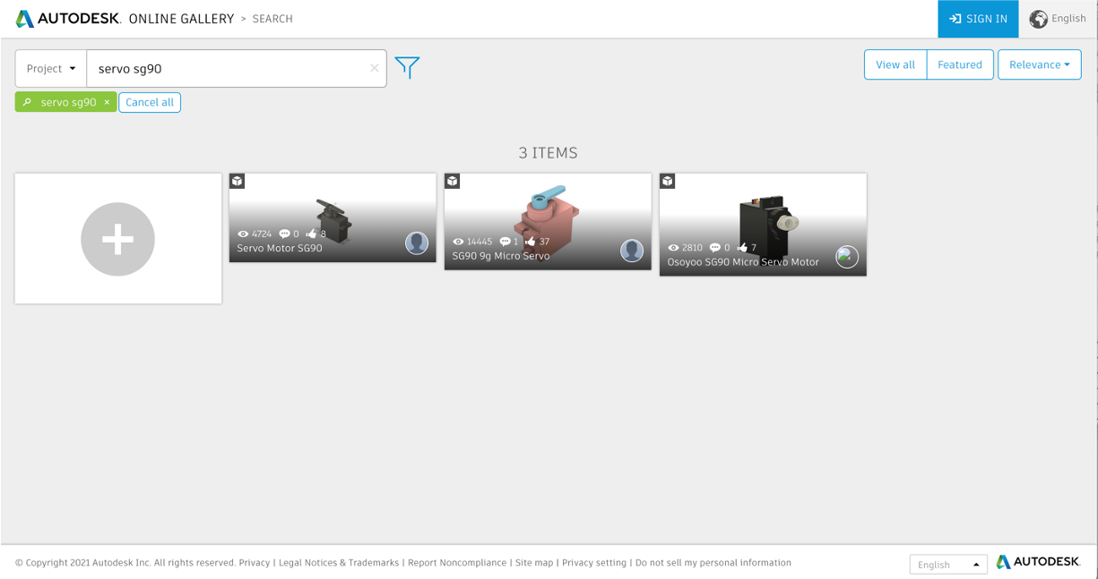
There are two main places to look for models - SketchFab and the Autodesk Gallery
Insert Mesh
For this walk through we have provided the mesh of an SG90 in STL format here
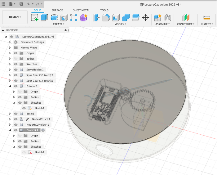
Activate the main scene (to ensure the mesh becomes part of the hierarchy)
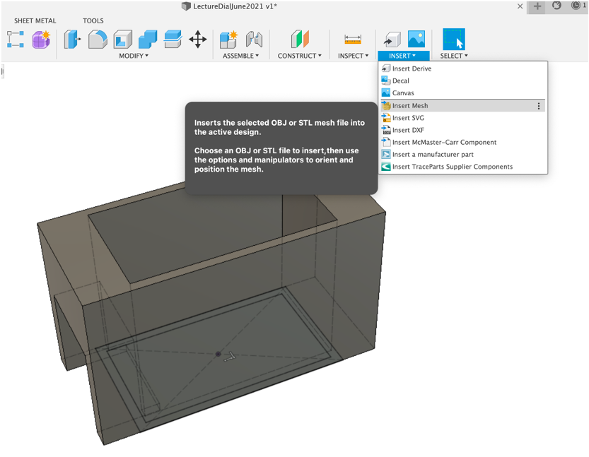
Insert and insert mesh - (SG90_OnlyServo.stl)
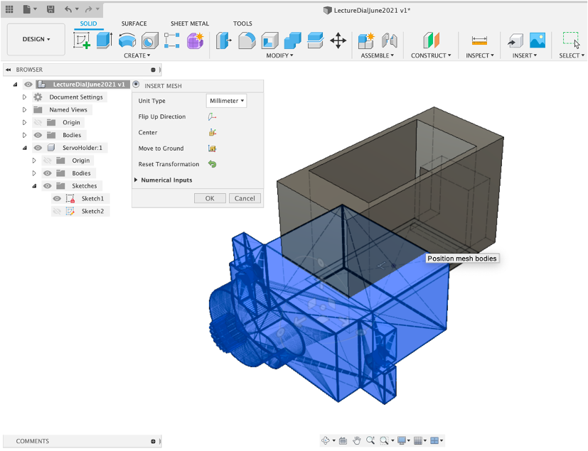
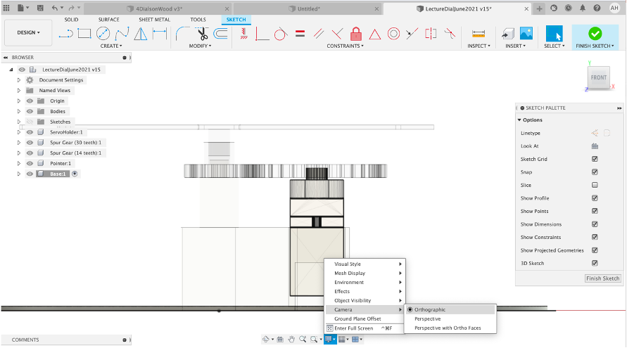
Align the model using the rotate/move arrows using the top/side views. Rename the mesh and note it has been added inside the Bodies tab, as its a mesh. As needs be change the camera to Orthographic (see the middle bottom ‘monitor icon' and then Camera).
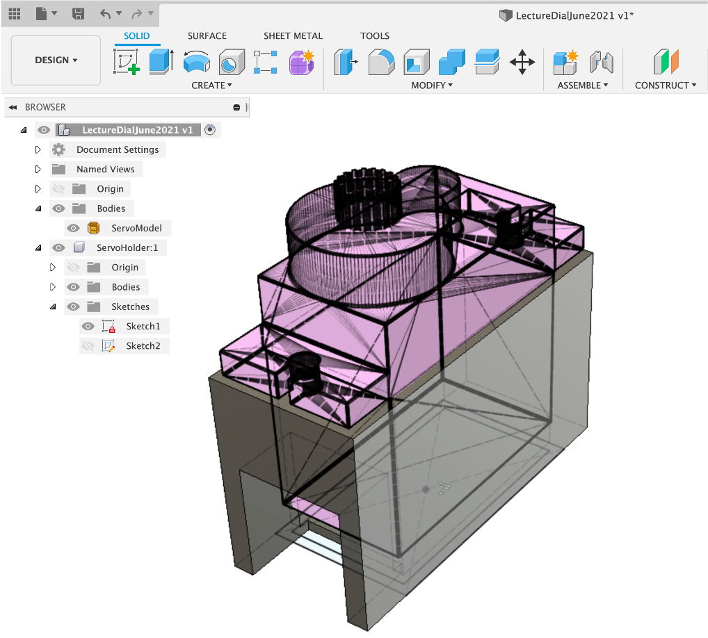
We use the servo as a reference point for the next part - adding the Gears.
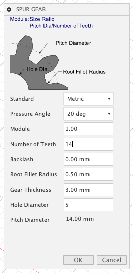
The SG90 Servo rotates by 180 degrees. A gear ratio of 2:1 provides a 360 degree rotation - so a main gear of 30 teeth and secondary gear of 15.
However, as not all servos were made equal it is wise to go over 360 degrees. 2:14 to 1 - 30:14. This allows 385 degrees which allows enough play to calibrate the servo.
Fusion adds new objects depending on the selected hierarchy - make sure your ‘top/root' level is highlighted.
Fusion has its own Gear Maker - Select Utilities -> Add-Ins -> Scripts and Add-ins, choose the _Python Spur Gear and Run
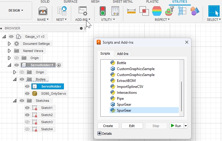
Type in the following settings and press OK, Fusion360 will automatically create the Gear as New Component
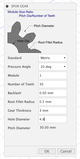
- Pressure Angle - there are three options - 14.5, 20 and 25. 25 provides more pressure but also noise, 20 is a good mid point to use on most projects.
- Module - Indicates how large/small the gear is - the module needs to be the same setting for all interlinking gears.
- Backlash - The tolerance between the gears. Ours is at 0 - through trial and error - the default is .15 and will also be ok.
- Radius - The size of the tooth
- Gear Thickness - simply the height of the gear
- Hole Diameter - the centre hole size - this is set at 4.8mm to allow a push fitting onto the servo.
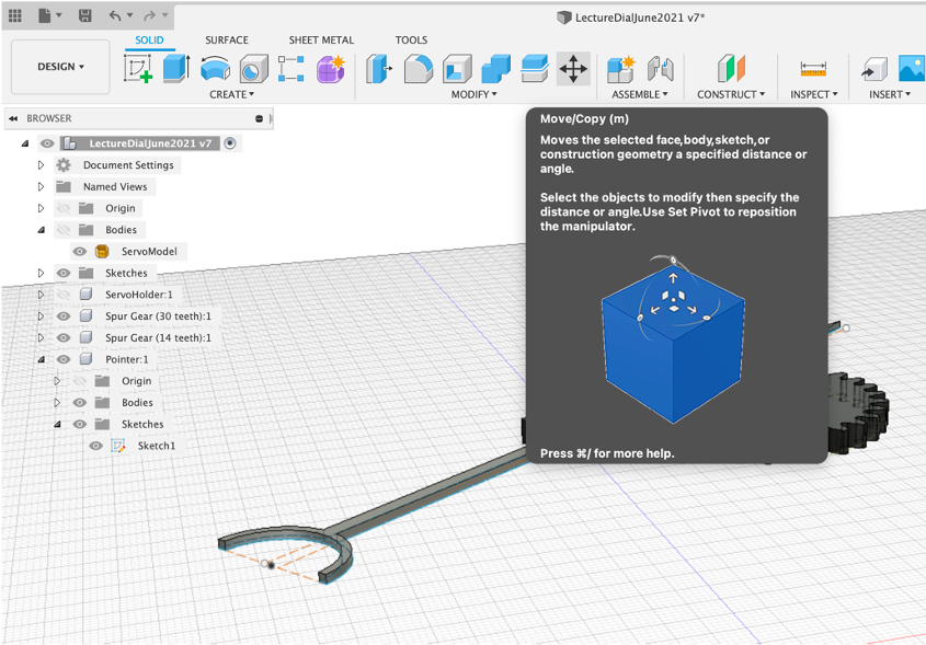
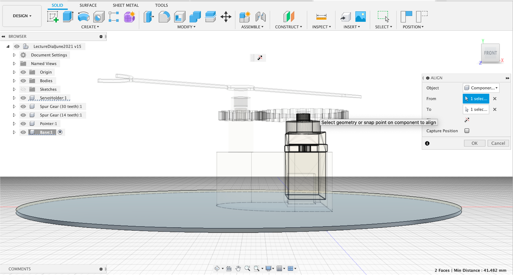
Use the Rotate/Move to align and select Capture Position future versions of Fusion will all an align with mesh option but this is still incoming (October, 2022). Press OK to confirm the new position
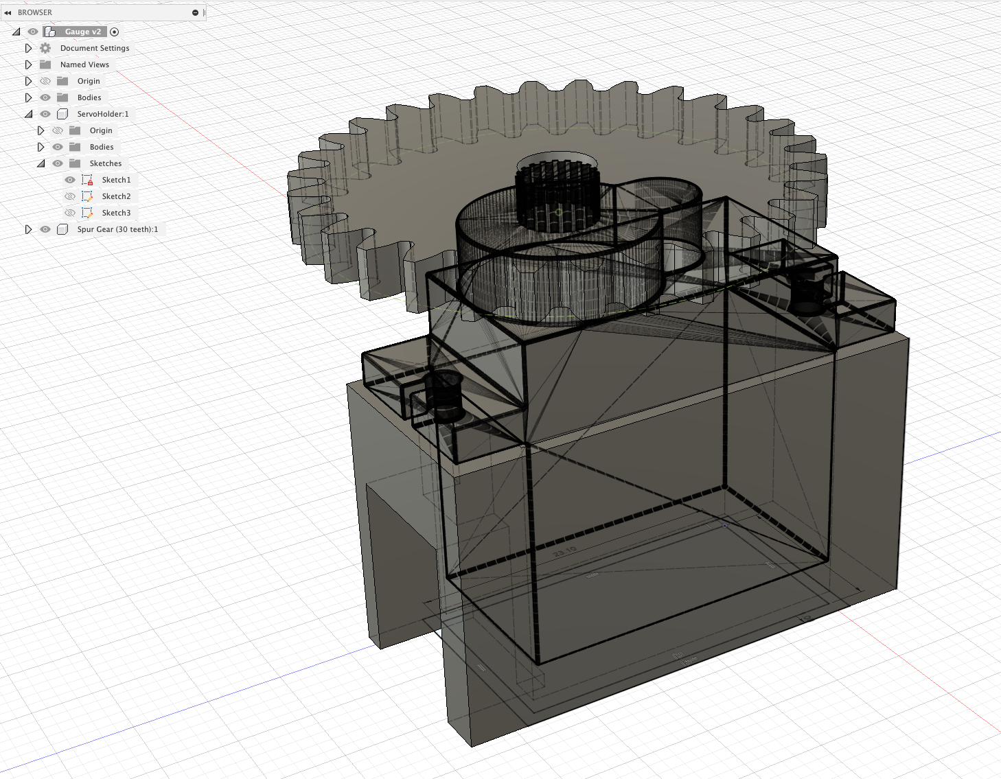
Our alignment is suitable for the level of accuracy required.
Gauge Gear
We need to create the second Gauge Gear, once again Tools: Add-Ins - Spur Gear, Run. Settings as below,
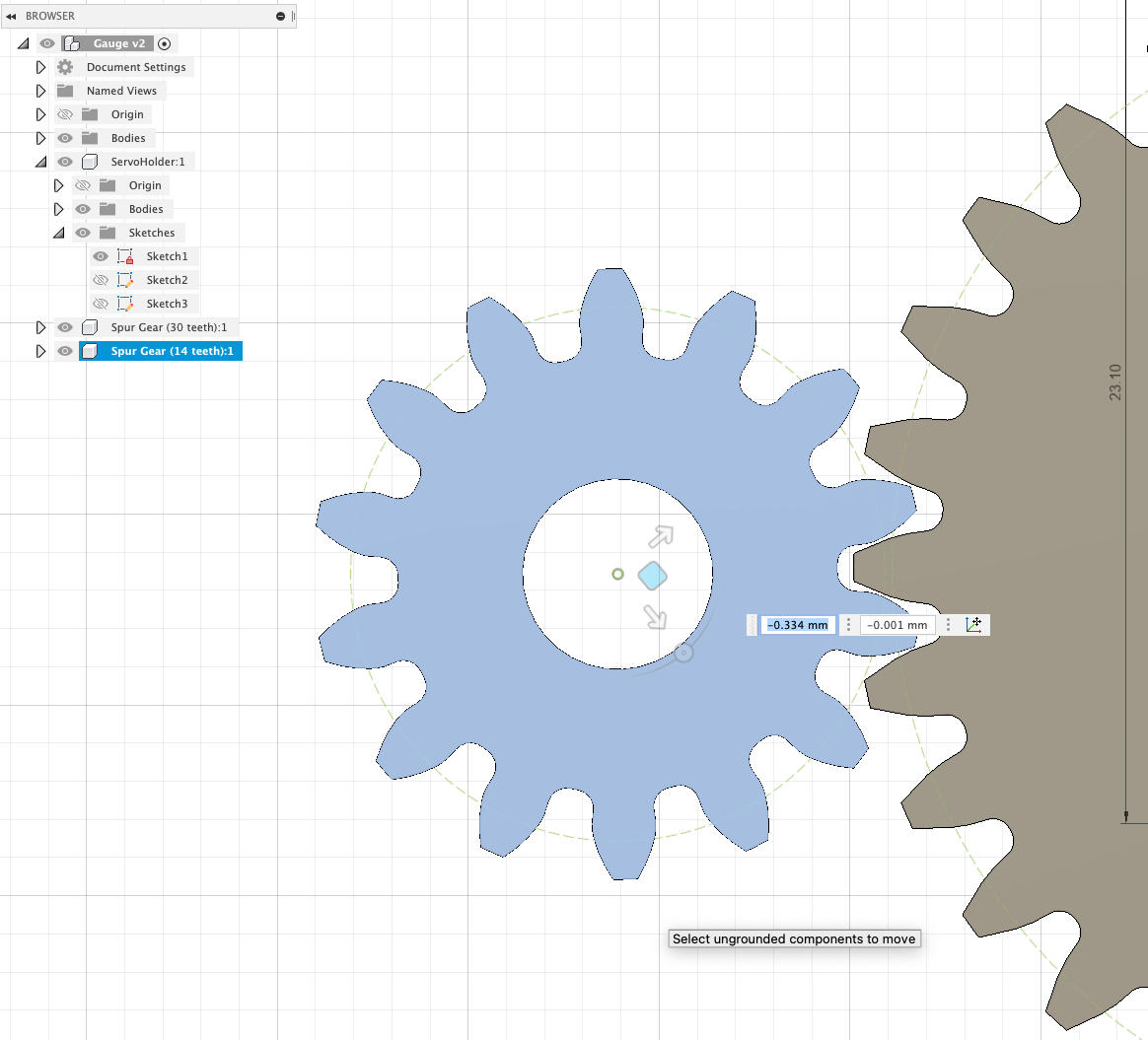
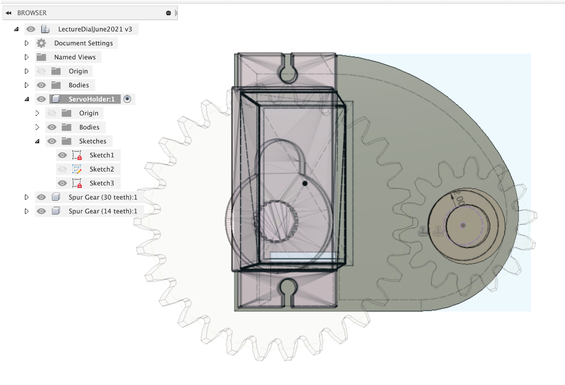
Rotate and move the Gear so the spurs intersect (to the left of the front of the Servo Holder with the Servo facing downwards). Make sure you select ‘Capture Position' after moving.
Making the Gear Shaft
We are going to use the edit the servo holder to also include the shaft to hold the second gear.
Press Pull on the side of the servo holder - pull so it extends beyond the gear - 24mm
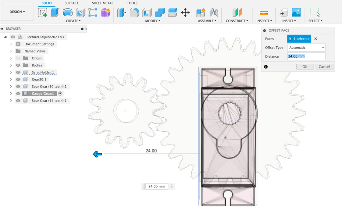
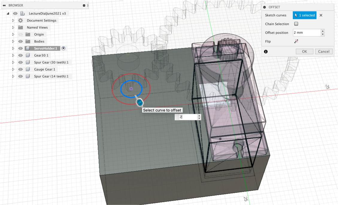
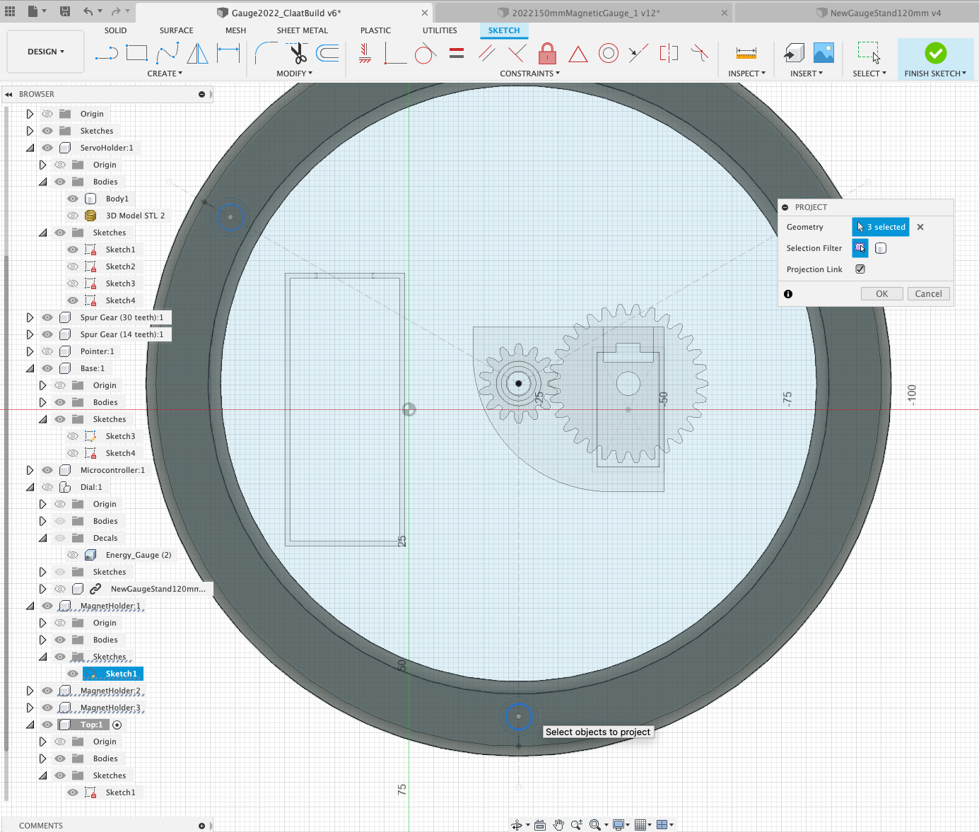
Projection
Projection is an extremely useful feature of Fusion 360. It allows any part of a model to be ‘projected' onto another surface, allowing it be sketched. We are going to project the gear hold onto the surface of the servo holder, to align the shaft.
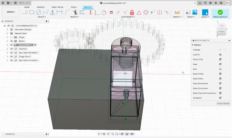
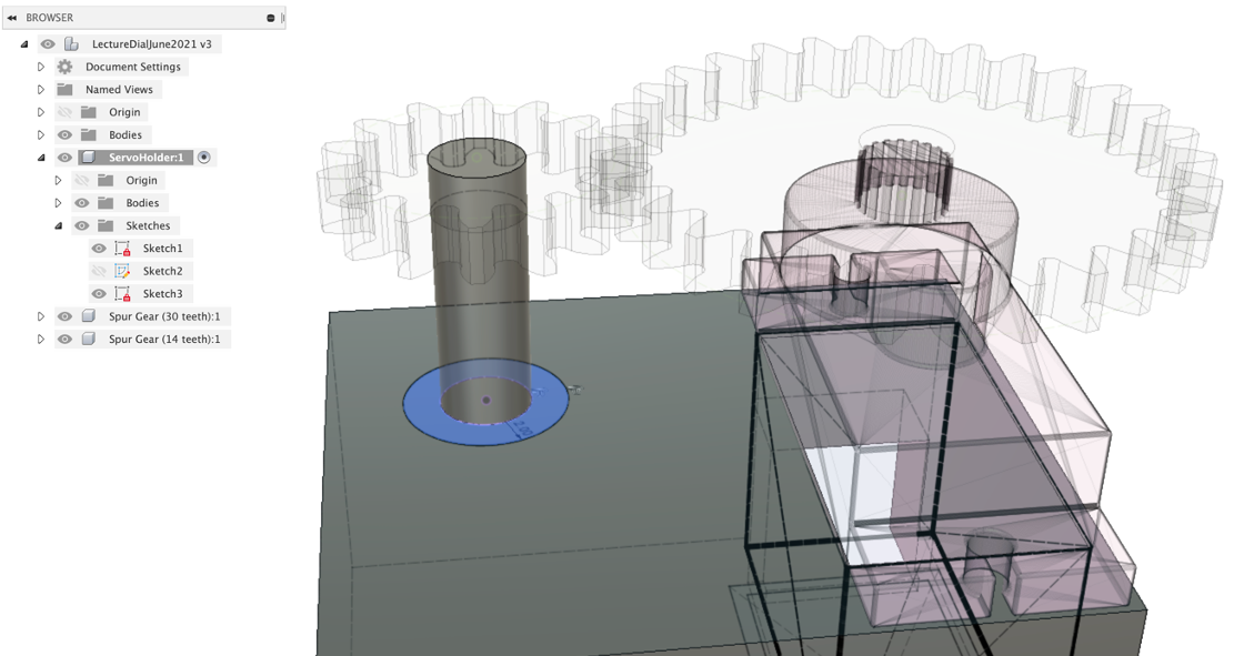
Active the servo holder and Create -> New Sketch on the top surface.
Create -> Project/Include -> Project Select the inner circle of the small Gauge Gear (click ‘OK' to confirm)
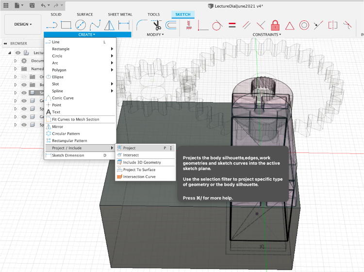
Offset by 2mm, this is go create a shaft on which the Gauge Gear will sit - again click ‘ok' to confirm.
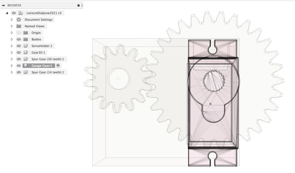
Press Pull to create the Central Shaft and hover the mouse over the Gauge Gear - it will snap to the height (zoom closer if not).
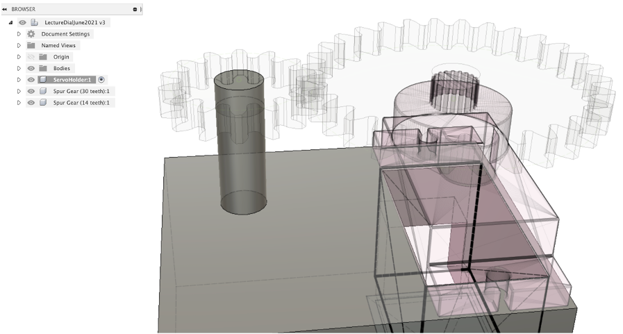
Reactivate your Sketch and Press Pull the outer offset - this time snap to the bottom of the gear
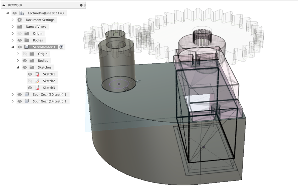
You now have two gears and a servo holder
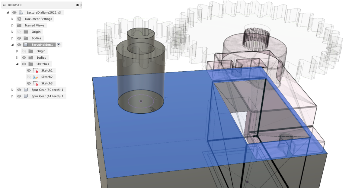
The final step is to remove some of the unused space and to refine the design.
Filleting adds a curved edge to an object, its a useful way to give a shape some definition after modelling.
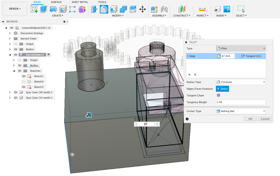
Select the corner vertical edge and tool/fillet (F to shortcut). Fillet according to your own preference.
Select the corner next to the Gear Shaft and again Fillet according to your preference.
The servo holder has now more than a square box - it has some shape and even though it will be hidden away in the physical version, in the augmented reality version it will be viewable for all to see.
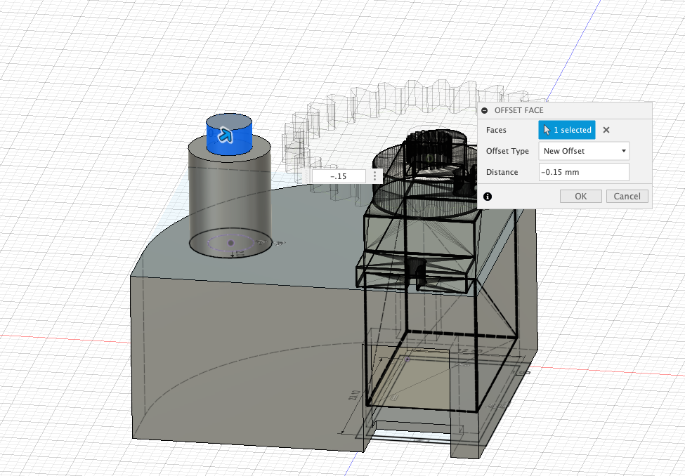
Finally in this section, we need the Gear to turn freely on the shaft and be close enough that it wont introduce any ‘wobble' to the gear when it is turning. Turn off the Gear Visibility (so you can see the gear shaft). Select the outer surface of the shaft and Press Pull by -0.15mm.
The data pointer (or needle - depending on your choice of term) is central to the overall look of the gauge. It needs fit into the gear so it moves, but not too tightly that it cant be taken out and realigned for calibration.
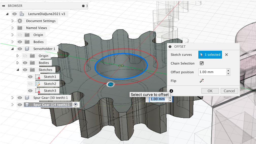
The pointer sits on top of the Gauge Gear - Select the 14 teeth gear and Offset by 1mm to create a ring wall followed by ‘OK').
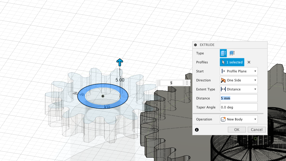
Press Pull by 5mm to extrude
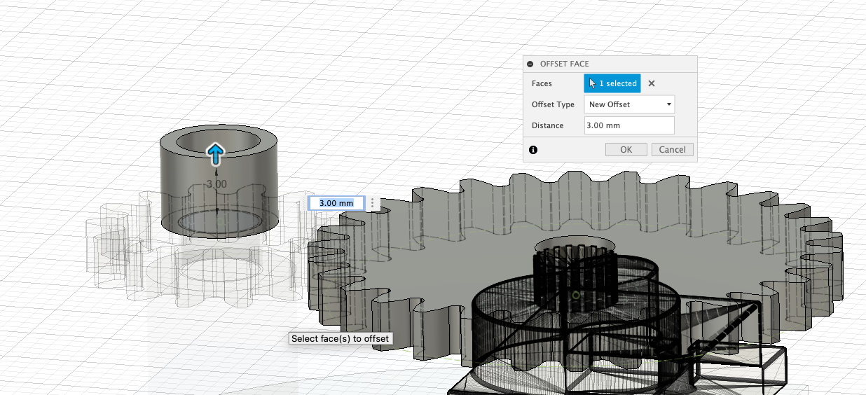
Finally we need to pull up the central shaft - to reduce any movement in the gear. Select the shaft and Press Pull3mm.
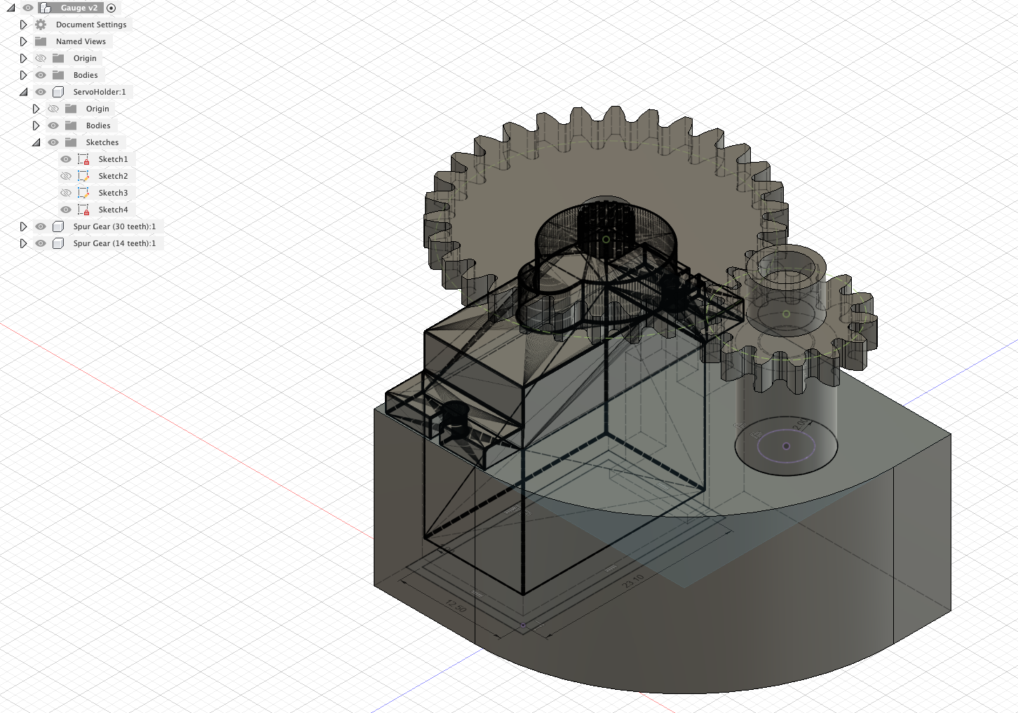
The first iteration of the Servo Holder and Gear Train is complete - well done. Make sure you save your project.
Before we carry on with the modelling - the Pointer/Needle is the next logical step - we are going to pause and explore the 3D Print Process and Rendering in Fusion 360.
Models from Fusion 360 can be exported for 3D printing (.stl format) via the Make tab.
This section assumes an basic knowledge of 3D printing on the Prusa printers.
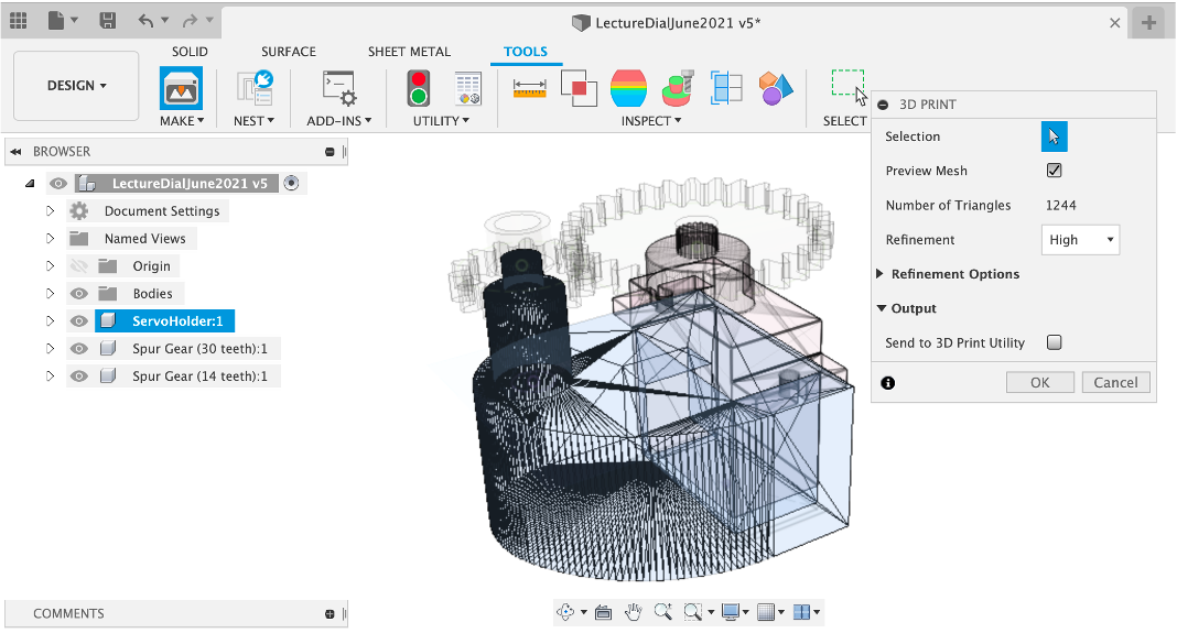
Select Make -> 3D print
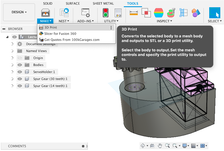
And then select the Component to export (they need to be exported one by one, without, of course, the reference model of the servo) and untick the Send to 3D Print Utility option and select RefinementHigh. This allows your to save the file directly to disk and open in your Slicer of choice.
We are using Slicer by Prusa for the course - Will will be running an intro to 3D printing workshop with you.
Large objects can be printed at 0.3mm resolution, small objects such as the gears/pointer should be printed at 0.2mm resolution and if there are any issues with the print, reprint at 80% speed.
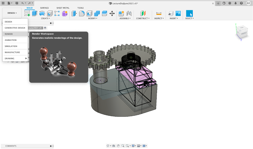
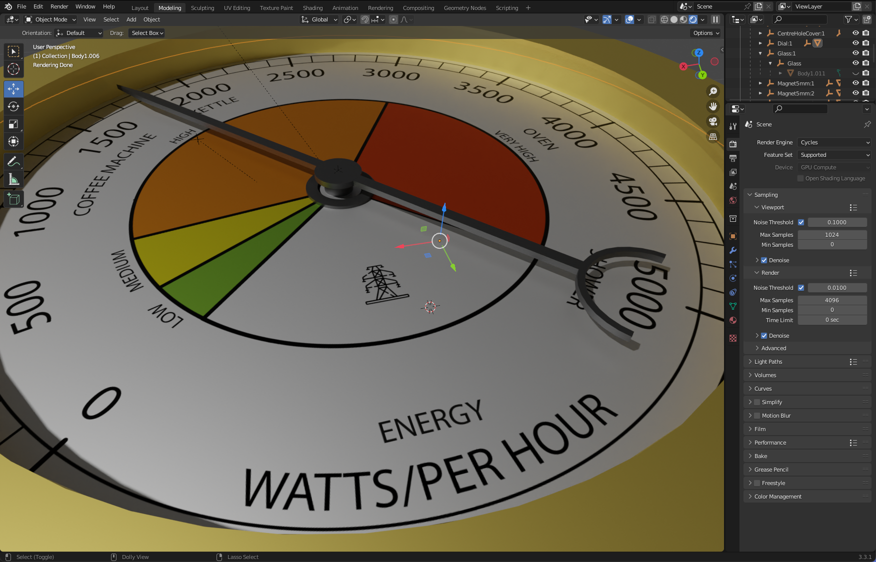
Fusion 360 has a powerful built in render engine. Oddly it only works with single images or motion studies rather than full animation. It is however worth taking 10 minutes to learn how it works.
Open the Render Work Space
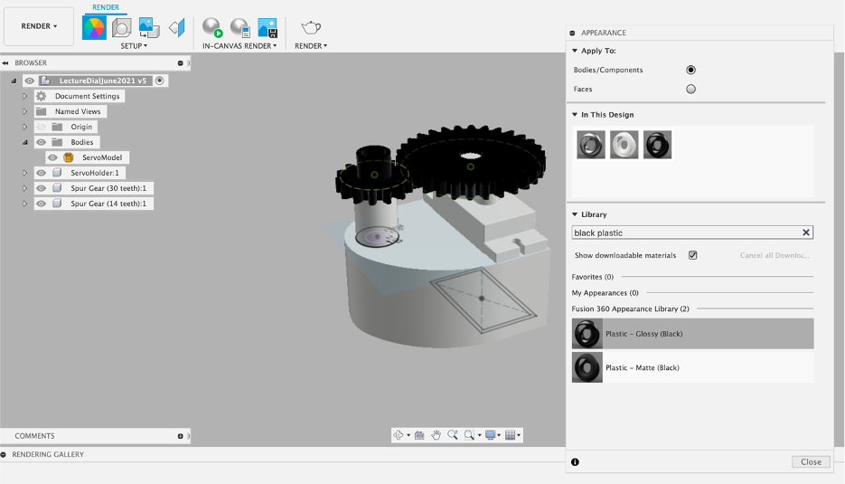
Setup - Appearance this is where we assign materials to our model.
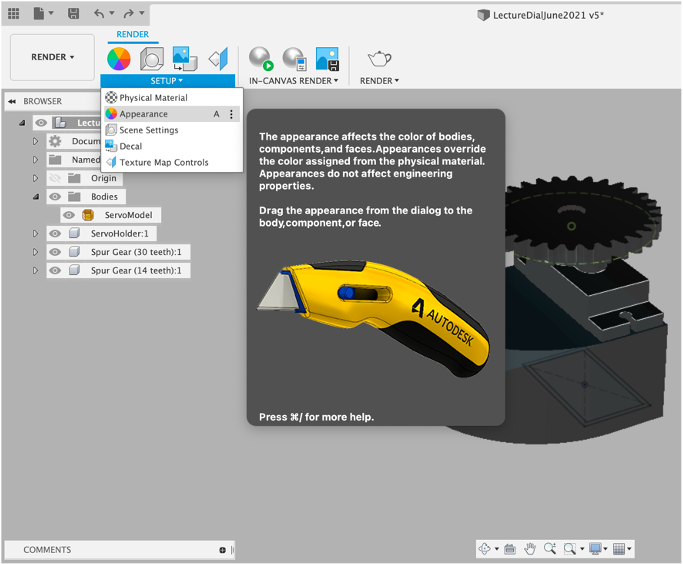
Search for White Plastic.
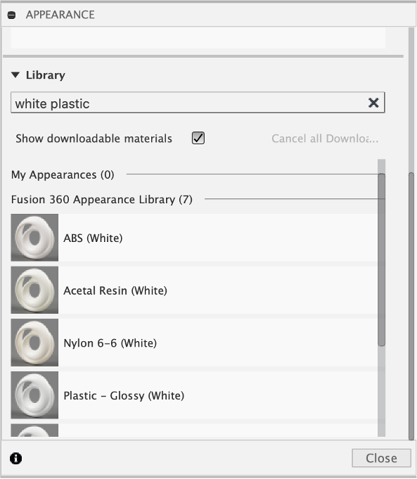
Click and Drag onto your objects. Add additional materials to your gears, i.e. Black Plastic.
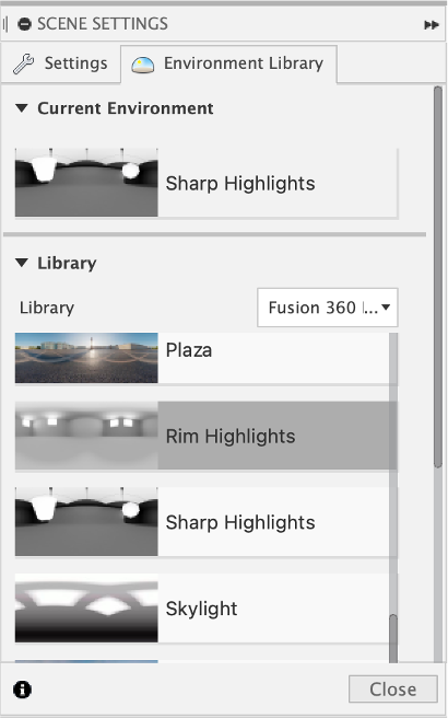
We now need lighting added to our scene. Open the Scene Settings dialog.
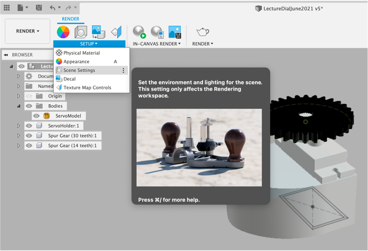
Click and Drag onto an option from the Environment Library into the scene (you may need to click the download arrow first) - light direction/background can be changed in the settings. Lakebed is good for shadows. You can also add custom High Dynamic Environments - see Poly Haven https://polyhaven.com/hdris for good examples to download.
To be able see the effects of the settings you need to set the In Canvas Render to Play.
For a more detailed Redner - Select Render from the top menu. Rendering can be carried out either via the Cloud, Locally or..
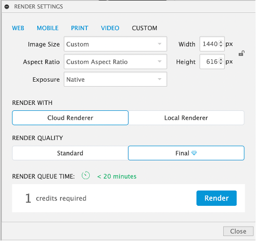
directly in the fusion, workspace. This allows your to quickly check lighting and shadows before running a full render.
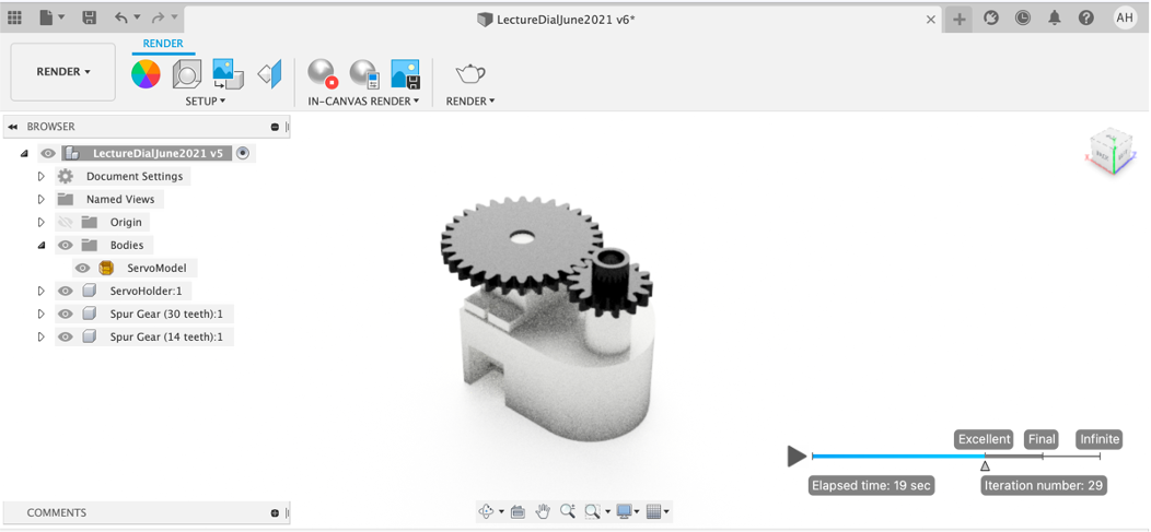
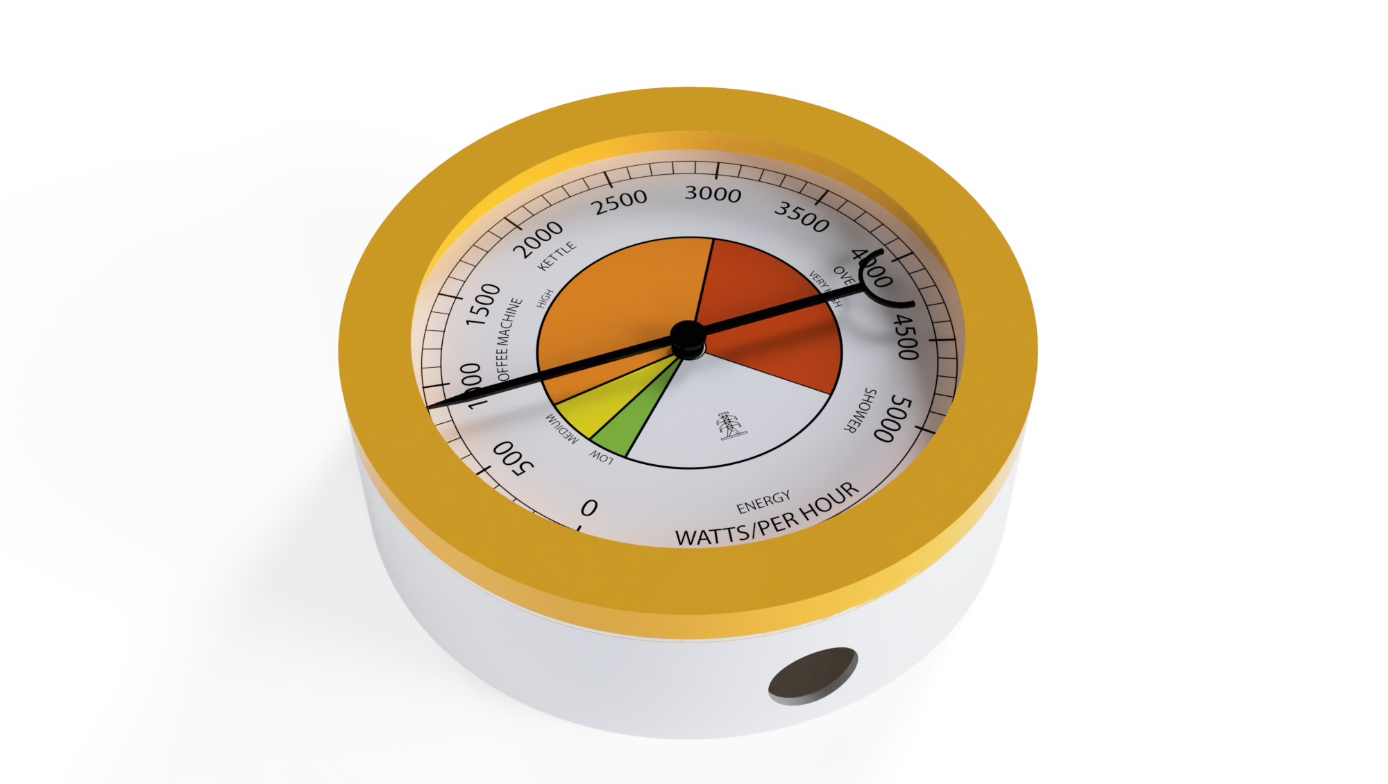
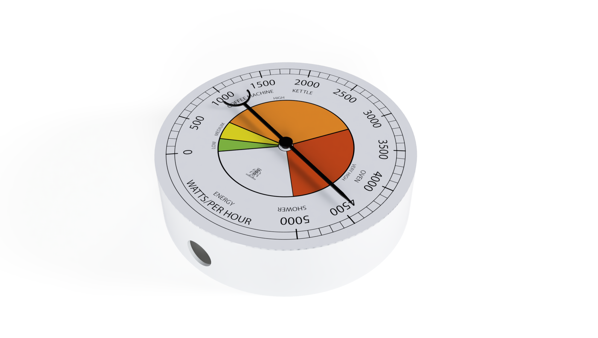
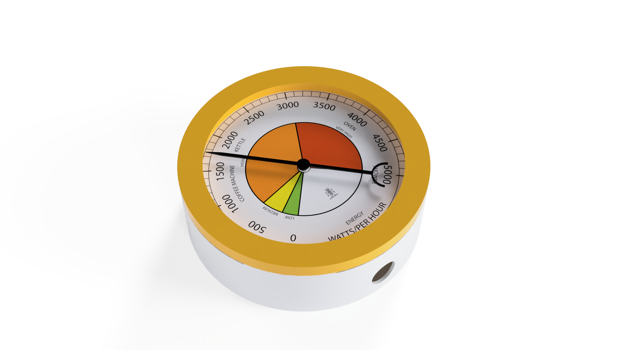
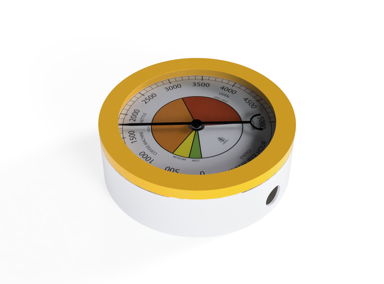
Rendering, either locally or via the cloud provide the following type of output. We use these settings throughout the next steps of 3D modelling.

Concept -
- Adaptable for a variety of gauge sizes.
- Needs to fit into the Main Gauge Gear

Additional Fusion 360 concepts covered in this section:
- Lines
- Arcs
- Trim
- Move

Head back to the ‘Design' view. The workspace is becoming a little crowded at this point so objects can be turned on and off (via the eye icons) to provide a clearer view.
Make sure you have the top/parent selected and create a New Component and rename it Pointer (or Needle, Indicator - what ever you choose). Create Sketch.
We will follow a series of steps here but feel free to design your own ‘Pointer' you will see that the examples around the lab have a number of different styles.
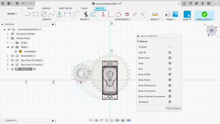
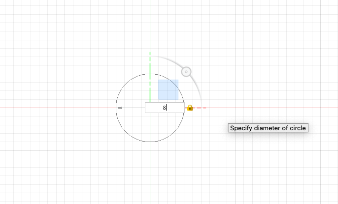
Create - Circle - Centre Diameter Circle
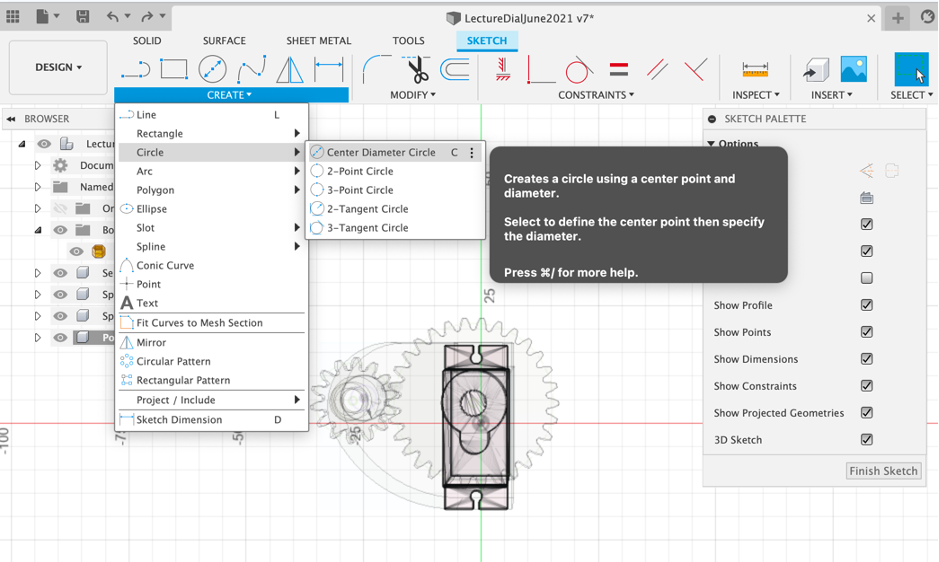
Make it 8mm in size
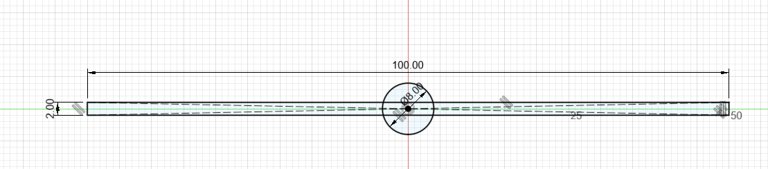
Now go to Create - Rectangle - Centre Rectangle and drag from the centre of the circle.
Make it 2mm by 100mm
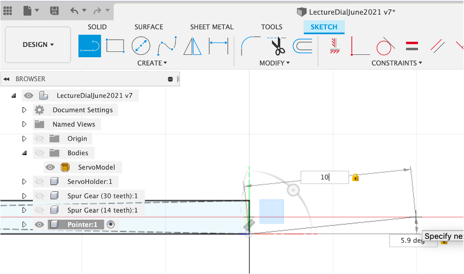
Go to Create and Line - Note there are various line types, including Construction Lines, which are useful as guidelines for projects. For now we are going to use the standard Line option.

Select the bottom point and hover over the red line to snap. Type in a length 10mm and draw another line to close the triangle.
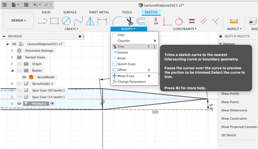
Select Tool - Trim - (t to shortcut) and Trim the 90 degree end line.
The Trim tool is useful to clean up sketches.
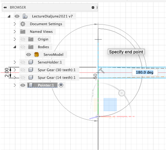
Zoom into the opposite end of the Pointer and go to Create - Arc - Centre Point Arc.
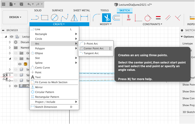
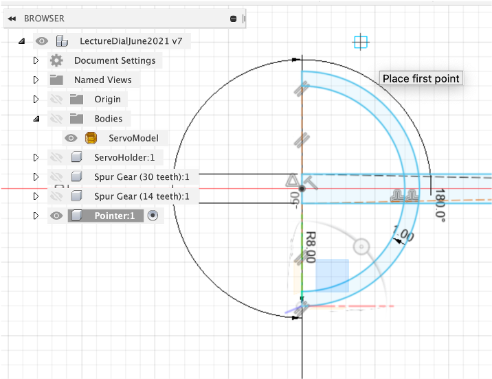
Click the Centre of the end of the pointer and drag out create an arc, set the size 8mm. Drag it round 180 degrees to complete the arc (hit ESC if needed to exit the Arc Function).
Offset the line by 1mm and close the end using the line tool.
Use Trim to tidy up the lines with the aim to create a single object - this requires all the intersecting points to be ‘trimmed'. Press Pull by 1mm to create the extruded pointer.
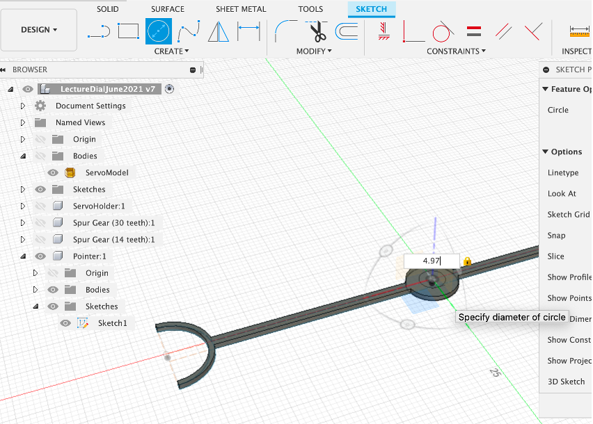
We now need to create a section on the pointer so it insects with the Gear. Create new Sketch and a Centre Point Circle of 4.97mm. We know the Gauge Gear has a 5mm holder, 0.3mm clearance allows a push fit.
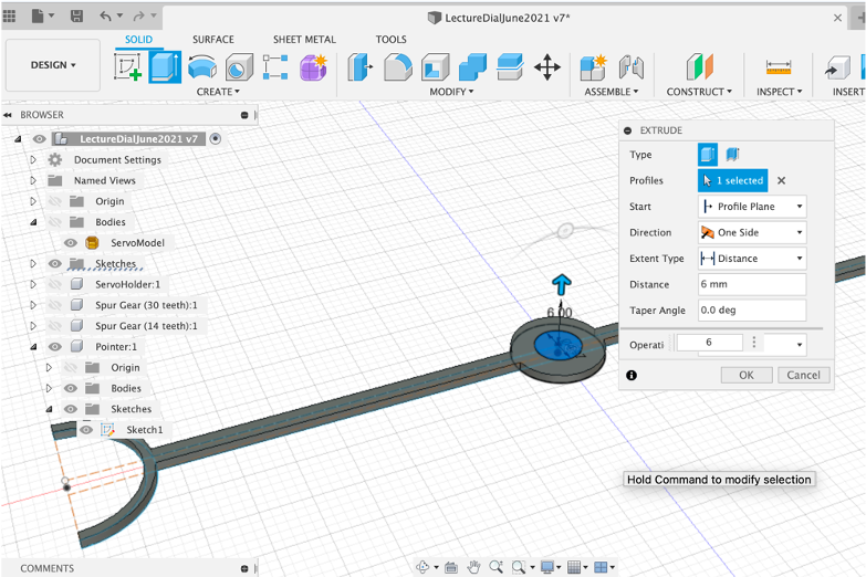
Press/Pull by 6mm - this will push into the Gauge Gear
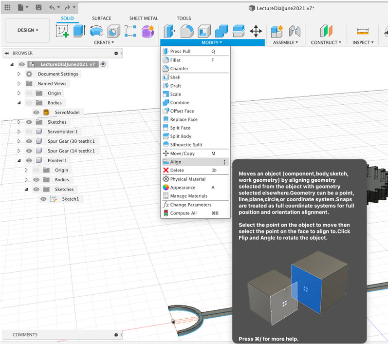
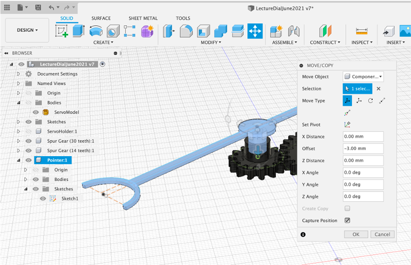
We now want to align it in place - select Modify - Align and Select the Centre Point of the Pointer.
Select the top of the Gauge Gear - the Pointer will snap into place (although upside down)
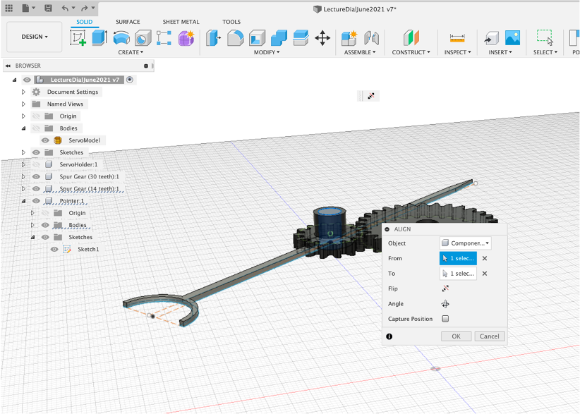
Select Move and ensure the Pointer is selected.
Rotate and move the Pointer into place.
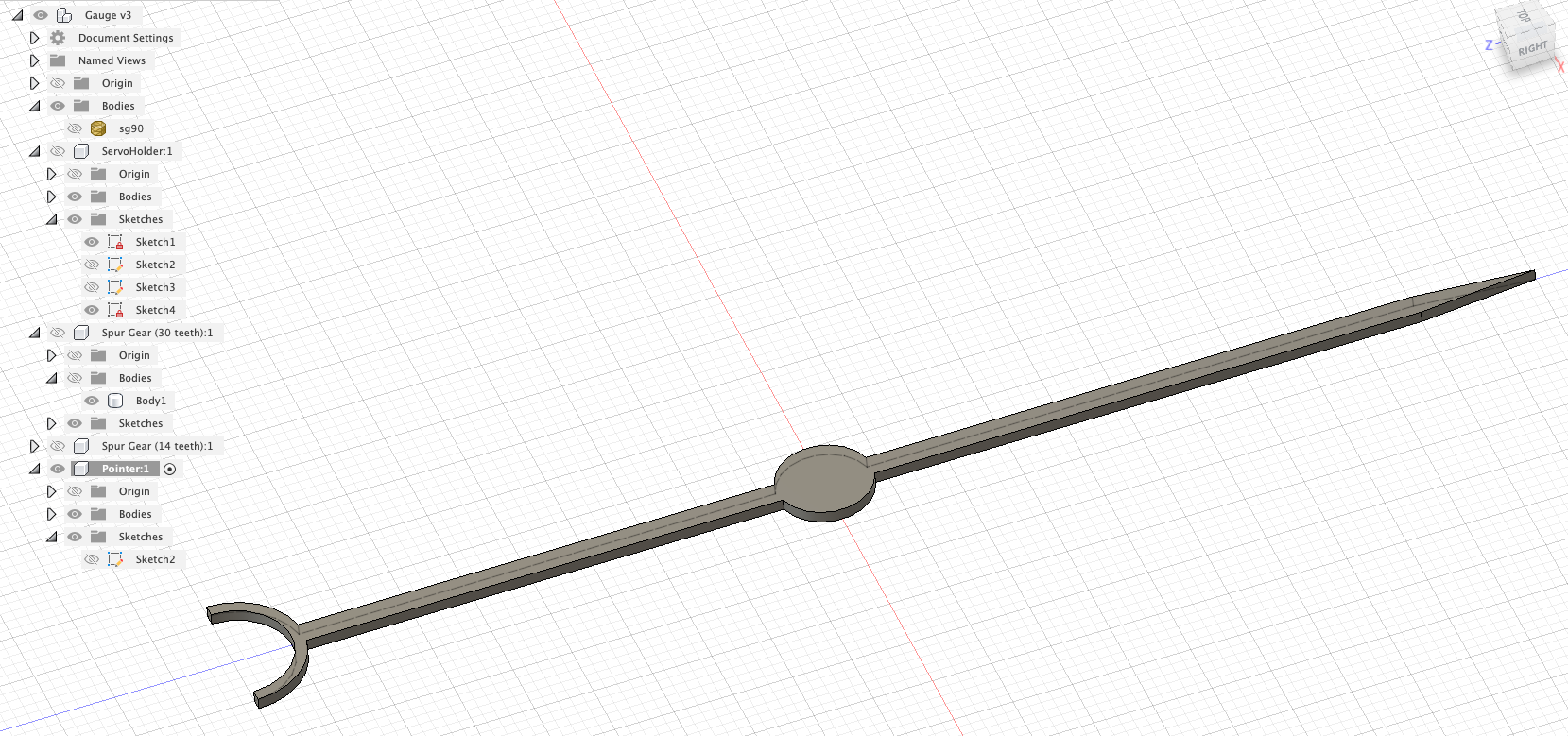
You now have a completed Servo Holder complete with a Gear Train and Pointer. We have covered the following concepts in Fusion 360 to reach this point:
- Lines
- Arcs
- Trim
- Components
- Sketches
- Offset
- Fillet
- Projection on Face
- Press/Pull
- Cut
- Spur Gears
- Importing Mesh
- Capture Position
- Visibility
- Rendering

We will reuse all of these concepts and add some more to make the rest of the Gauge.
We now have many of the key concepts in Fusion 360 covered, we are going to use these techniques to quickly build the Main Gauge - the main features we need to think about are:
- Size - the Gauge can be any size, limited only by the torque of the servo and the size of the print bed. Here we are going to use a size of 150mm as its a good comprise between a useable gauge and print time. In a perfect world you would use a slightly larger size, to make use of the full print bed.
- Does Gauge have a front cover - glass/acrylic?
- How will the front cover be attached to the main gauge? (We will use a Magnetic Catch system - this is useful for any number of lids/tops on enclosures).
- Does it need lighting and if so how is the lighting used so it is a soft diffused light keeping with the power limits of the Node MCU board. Can the lights be used to display additional data?
- The Gauge needs to hold the Node MCU/or Pi Pico W along with our Servo Holder with access to the power supply (USB Cables).
Additional concepts covered include
- Change Camera Type
- Importing from the Fusion 360 Gallery
- Using Decals - for the dial image
As with all 3D modelling, there are no right or wrong methods, merely many ways to reach the same end point. In the next steps we will be offsetting, pushing and pulling to create holder for the main components as well as ridges to hold the acrylic and extrusions to hold 3 magnets. Now you have the techniques in place such a model can be made and ready to print in under 30 minutes.
The Acrylic Front
Acrylic discs make a perfect material to use for the front of dials, they are lightweight but provide both protection and a certain look to the device. In addition they can be used to ‘tap' onto if you add in a vibration sensor - perhaps to trigger the showing of a High and Low data reading for the day. This harks back to the days of tapping a barometer as the pointer would often get stuck on small movements.
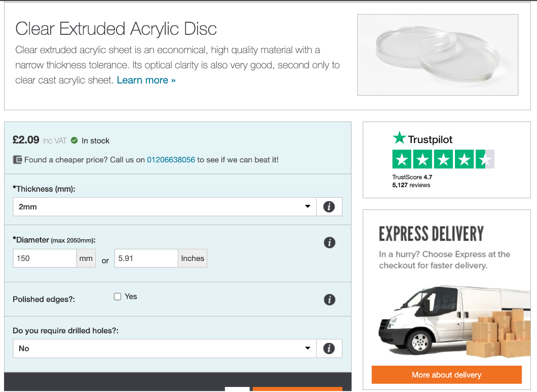
Simply Plastics is a great side for all things plastic and they provide a number of options on Acrylic discs.
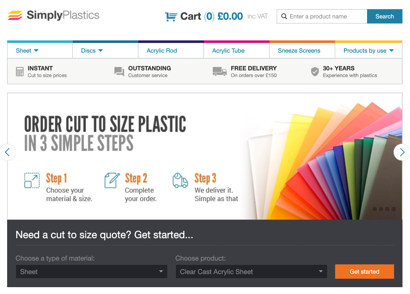
For our set up we used a 2mm thickness with a 125mm diameter - delivery time is approximately 5 days
Or of course - explore cutting your own at either the Bartlett or Pool Street Workshops (its much quicker and easy - draw a circle and ‘cut').
Main Gauge Base
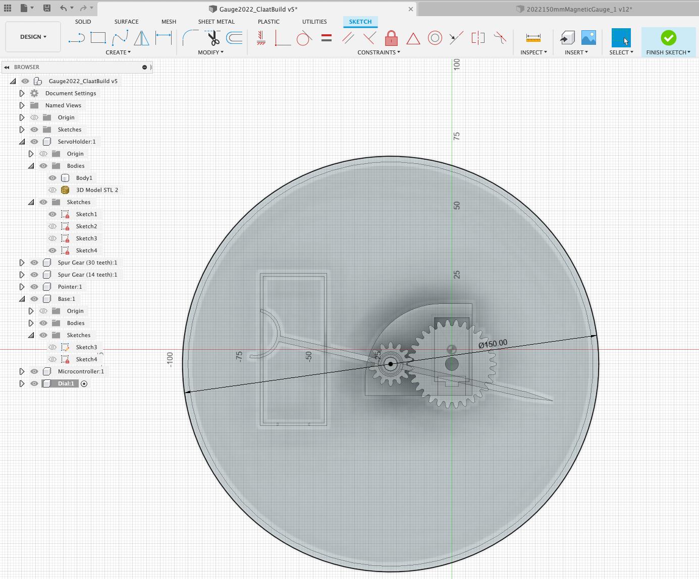
OK lets start the base by adding a New Component, name it and then Create Sketch and create a Centre Circle of 150mm to the left of the servo holder - we will align it in the next step to give us a new centre point to work from.
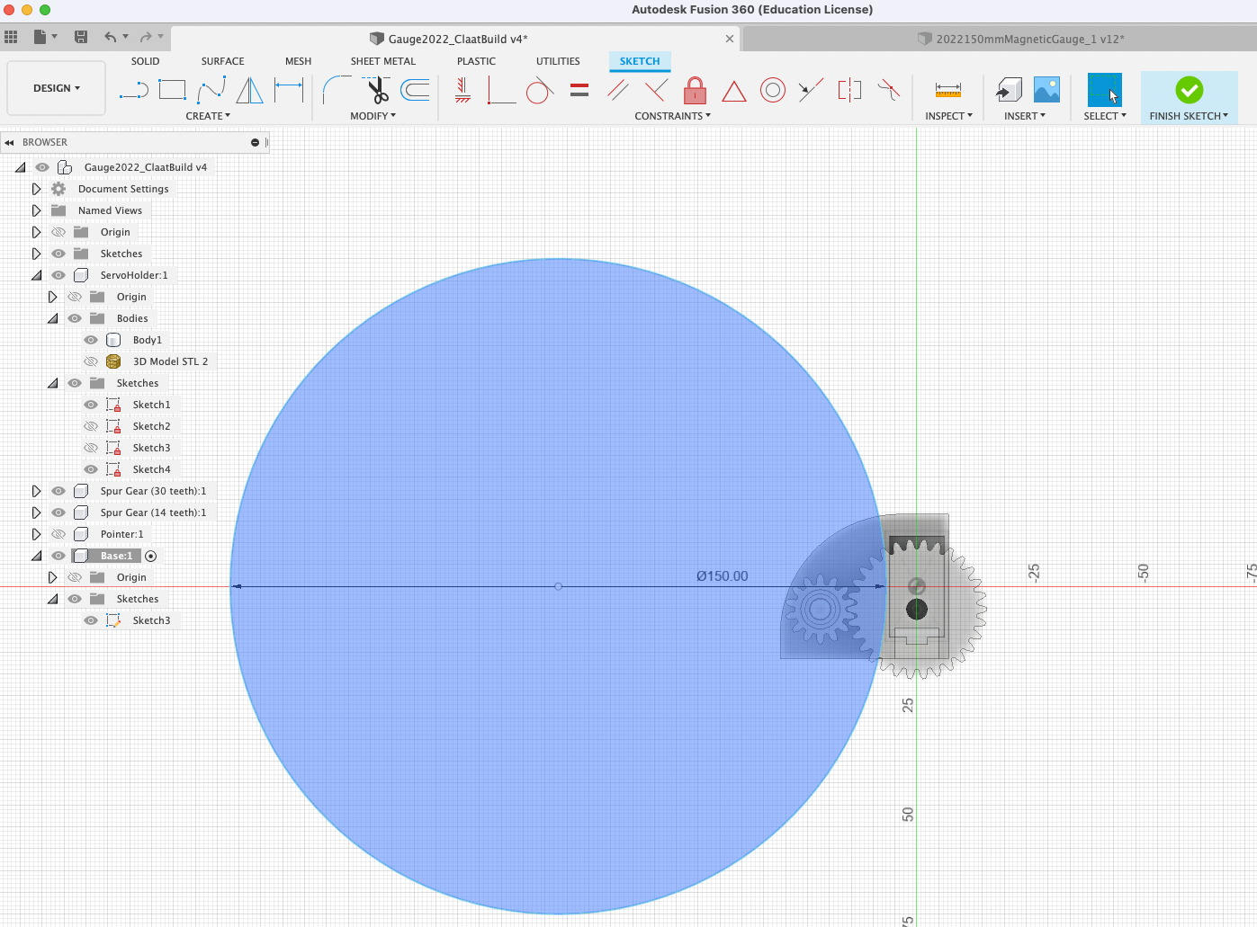
Press Pull 1mm to create a new body - this is our base, we will now align it with the centre of the 14 teeth spur gear. to ensure we have a centred model.
Press 'M' to Move the Base - we are going to use ‘Point to Point' - Select the Centre of the Base and the Centre of the Spur Gear (14 teeth). The base will now align with the central rotation point of the data pointer.
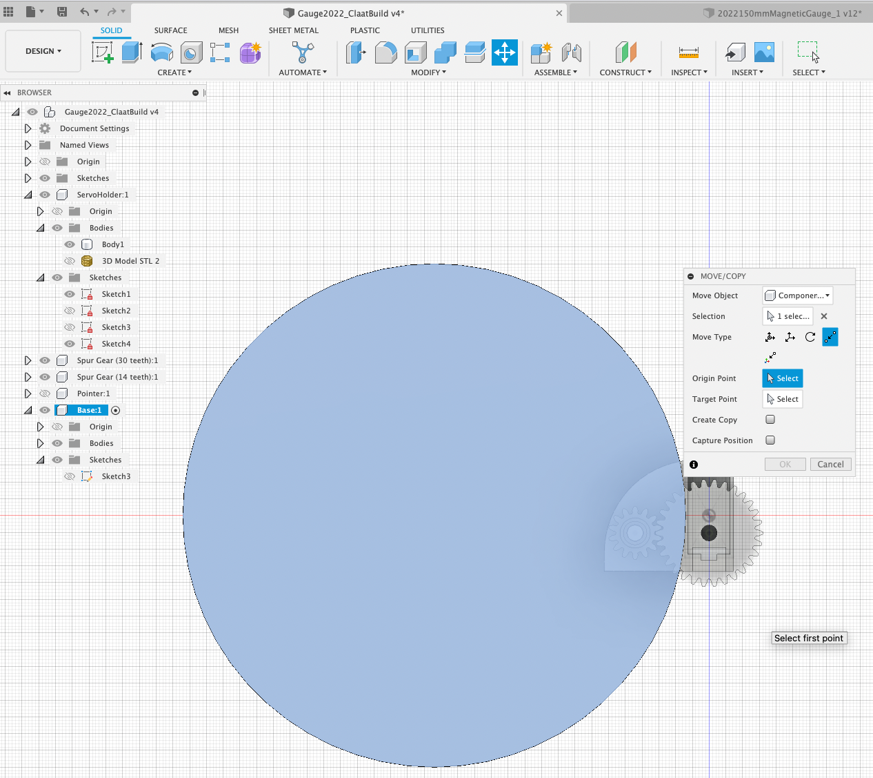
The base will now align with the central rotation point of the data pointer.
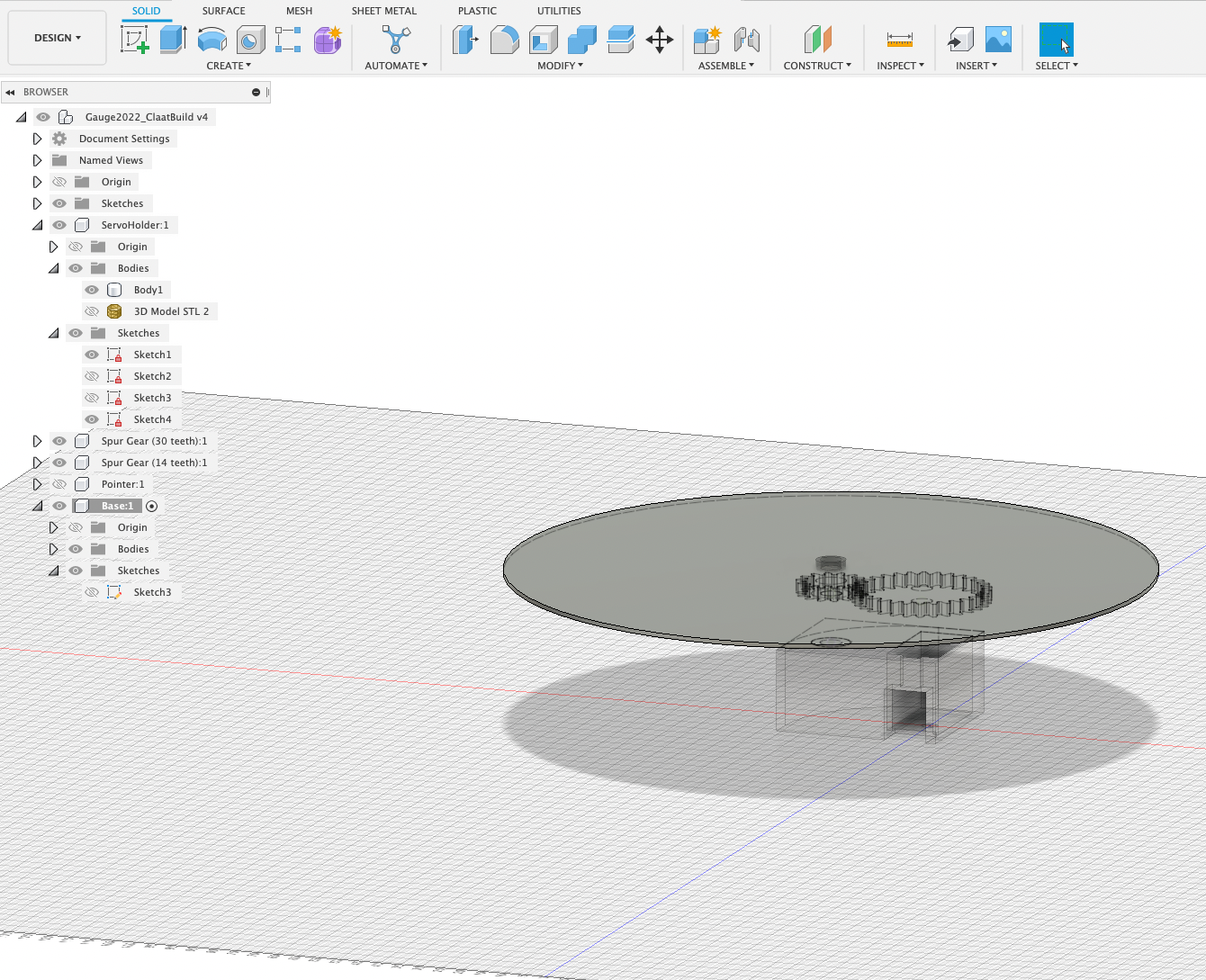
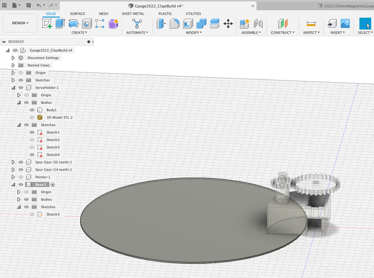
We now need to align the bottom of the base with the bottom of the servo holder - again Press 'M' to move. This time using the ‘Free Move' start moving and then click the top of the base and the bottom of the servo holder - both objects will now align. This is a useful technique to align objects (it takes a little getting used to).
You scene should look similar to the image below:
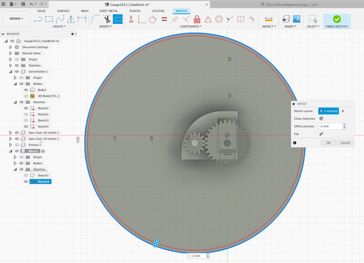
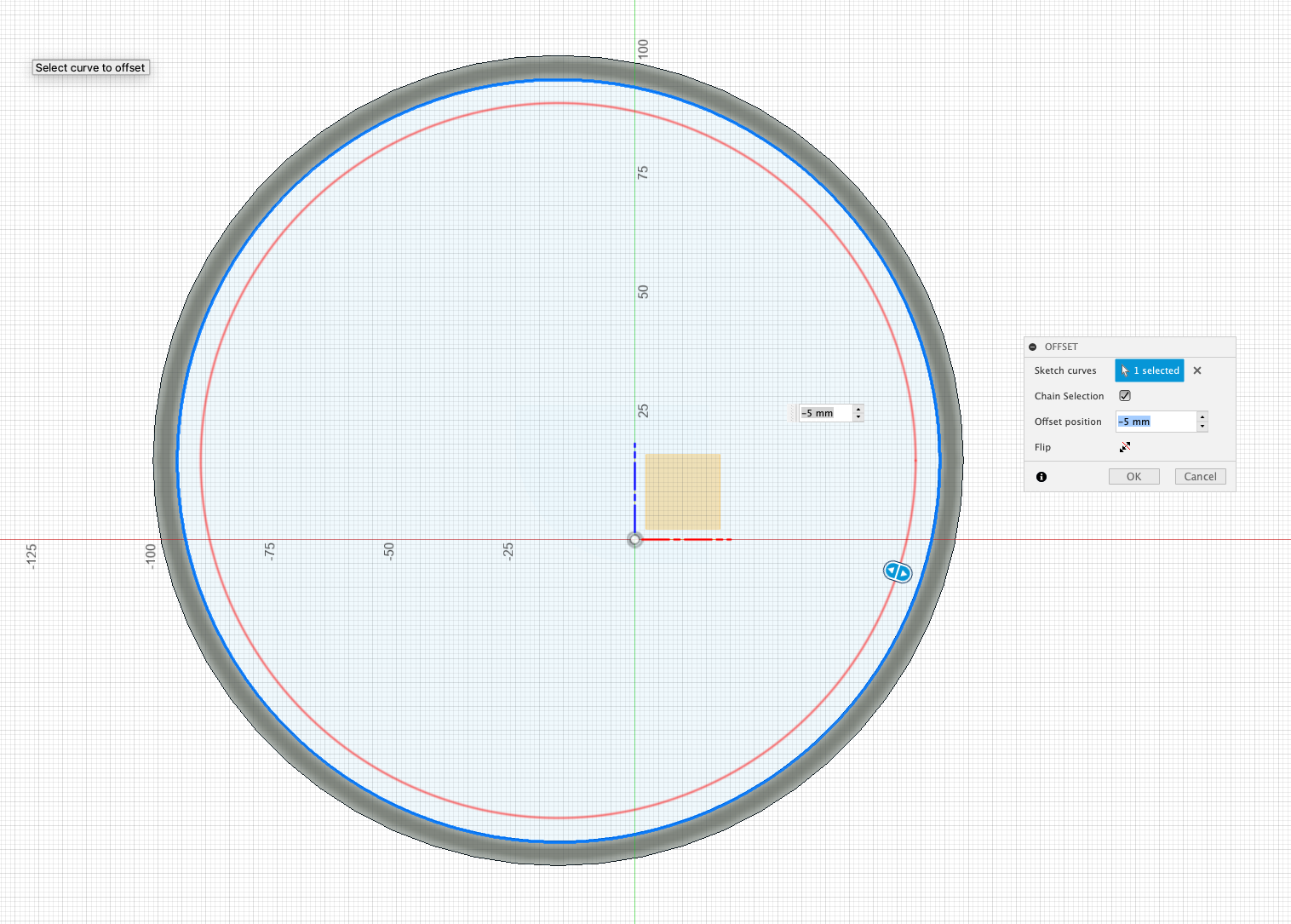
Select the Bottom Edge of the base and Offset by -2mm . This creates our inner wall.
Select the Front View and Change the Camera to Orthographic.
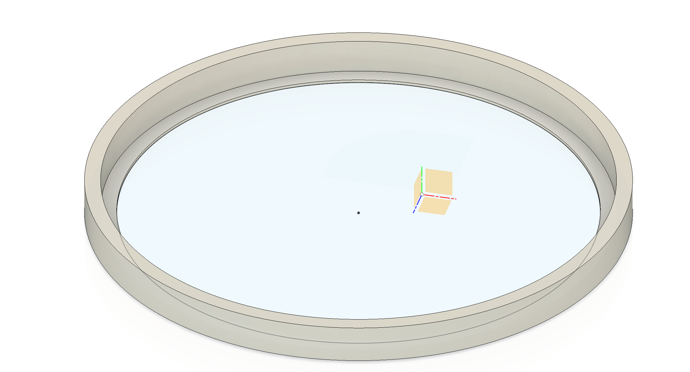
Rotate the Camera View to select the offset plane - switch back to Front View and Press/Pull-40mm - This pulls the side up just above the Gauge Gear - this is where the Dial will Sit.
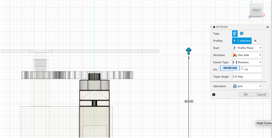
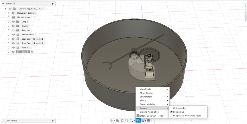
Change your Camera base to Perspective - you now have the base in place. Its a good time to save the model.
Node MCU Holder / Pi Pico Holder
Adding a holder for the micro-controller is simple a case of knowing the length/width and building a simple outline on the base of the gauge. These could be obtained from the specs online, or the best way is to simply use callipers.
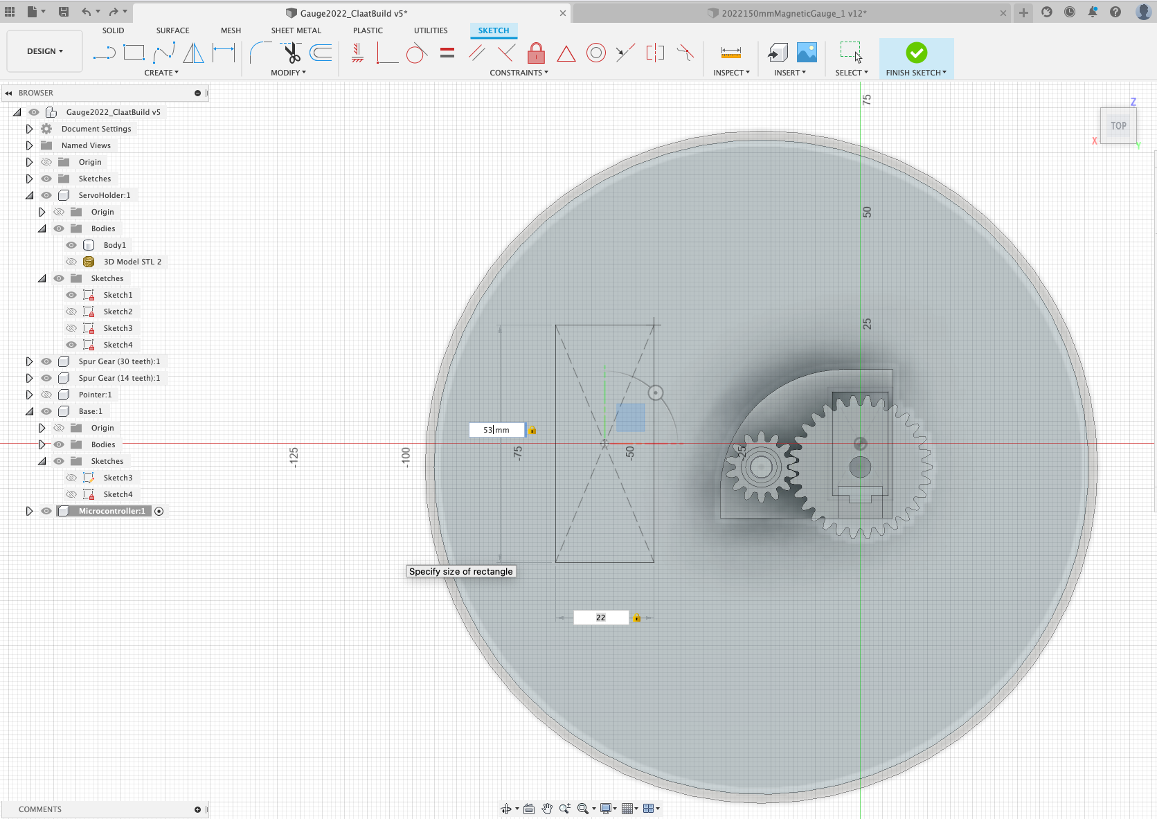
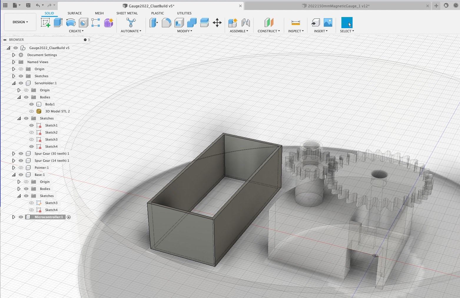
Create a ‘New Component', name it ‘microcontroller' and create a new sketch (i.e. the normal workflow) and add a ‘Centre Point Rectangle' to the left of the Servo - 22 x 53 for the Pico W (pictured) or 32 x 59 for the AZ Delivery NodeMCU.
Select the outline and offset ‘o' by 1mm
Select the outer wall and ‘Press/Pull' up - we used 18mm.
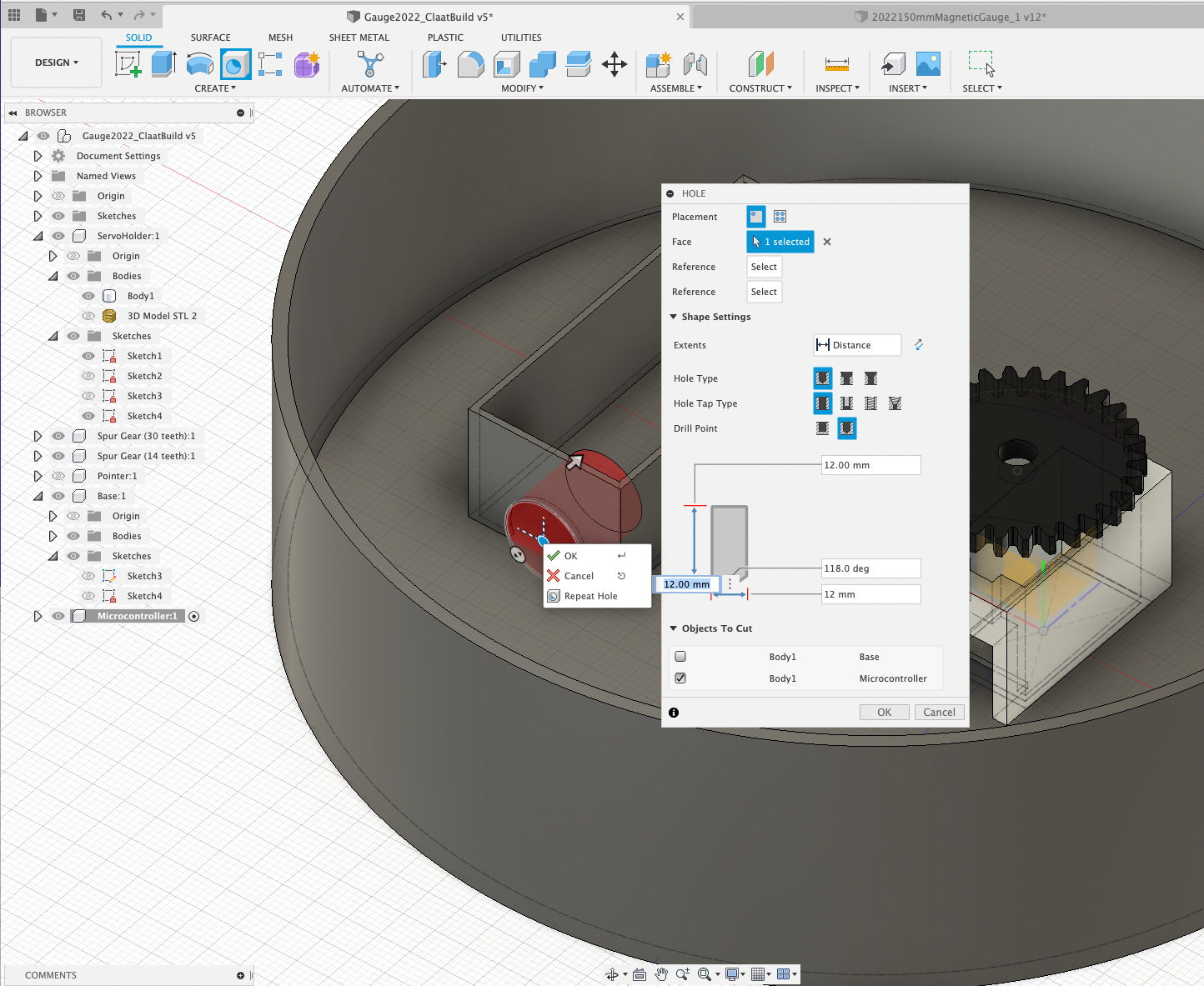
All we need now is a ‘Hole' for the USB cable to run in - we can use the Fusion 360 Hole tool. Make sure the Microcontroller component is select and click the hole tool - select the face and make the size 12mm (the size of a micro USB lead). One thing to note is the Hole Tool cuts through all bodies so you need to unselect the ‘Base' to ensure it only cuts where you want it to.
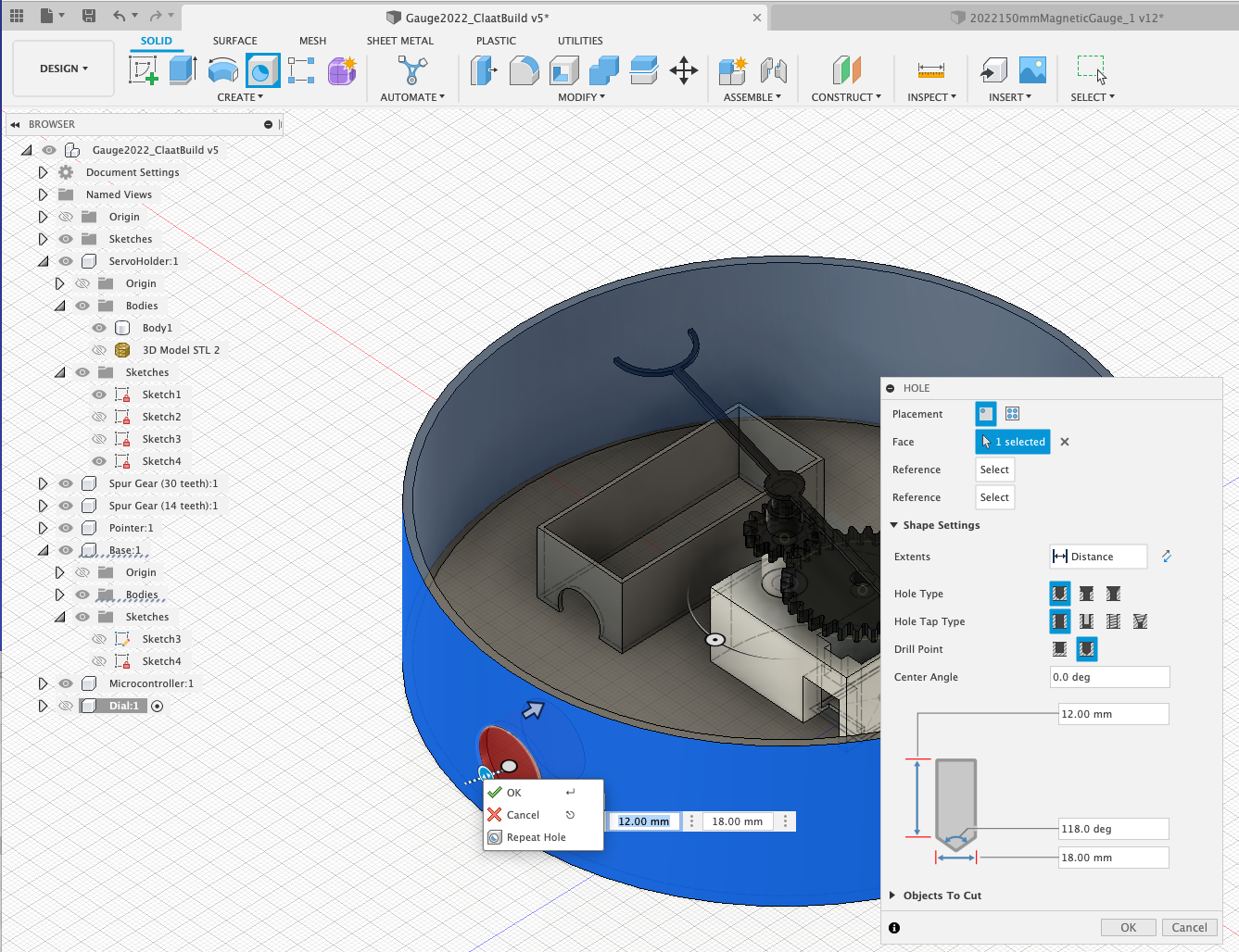
While was are using the ‘Hole' tool - repeat the process to add a whole at the bottom of the gauge, again for the USB Cable.
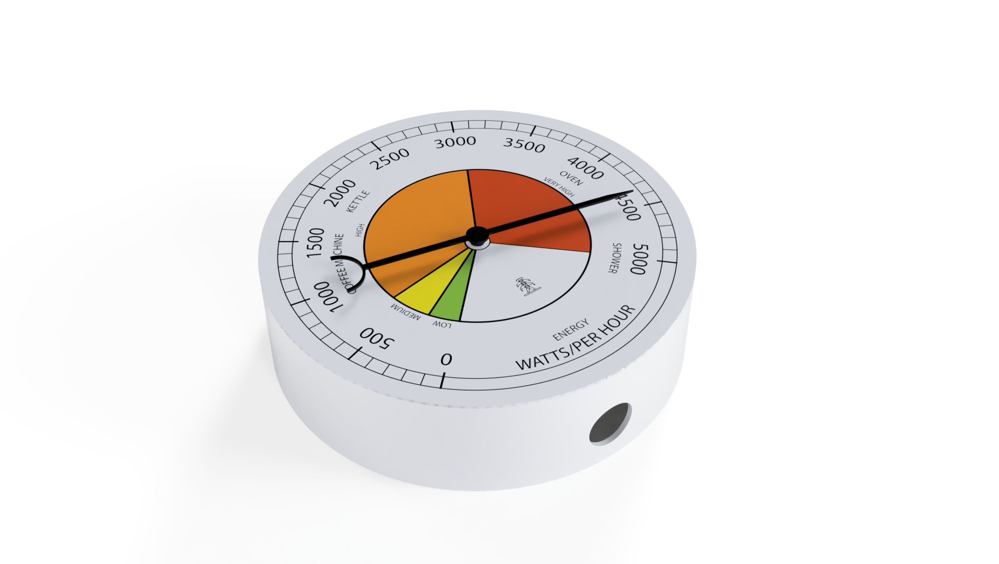
The Dial is interchangeable - because our Servo allows a 360 movement it can be adapted to any data you want to use. The dial was made in Adobe Illustrator, although any Vector package could be used (such as Figma or Inkscape - Figma is perhaps the easiest to use).
In this section we use the Fusion Decal function to import and place a texture while also creating the physical dial holder.
Create a New Component, name it (Dial), Create Sketch - Central Diameter Circle150mm.
Press/Pull1mm - this give us a base for the dial.
Move the Dial into place - just below the Pointer. Adjust the pointer up 1mm if required, so it sits above the dial.
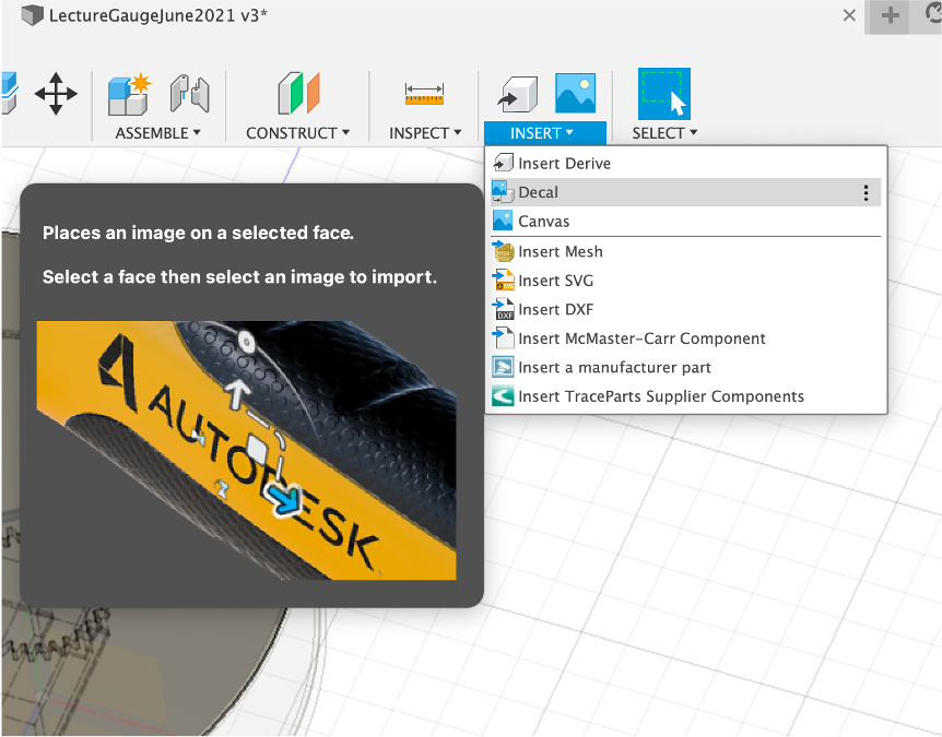
To insert the Decal first select your Dial of Choice graphic from Open Gauges and save to your laptop.
Insert -> Decal -> From my Computerand locate your dial - we are using ‘Energy_Gauge' for this example.
Select the top face of the Dial to place the image.
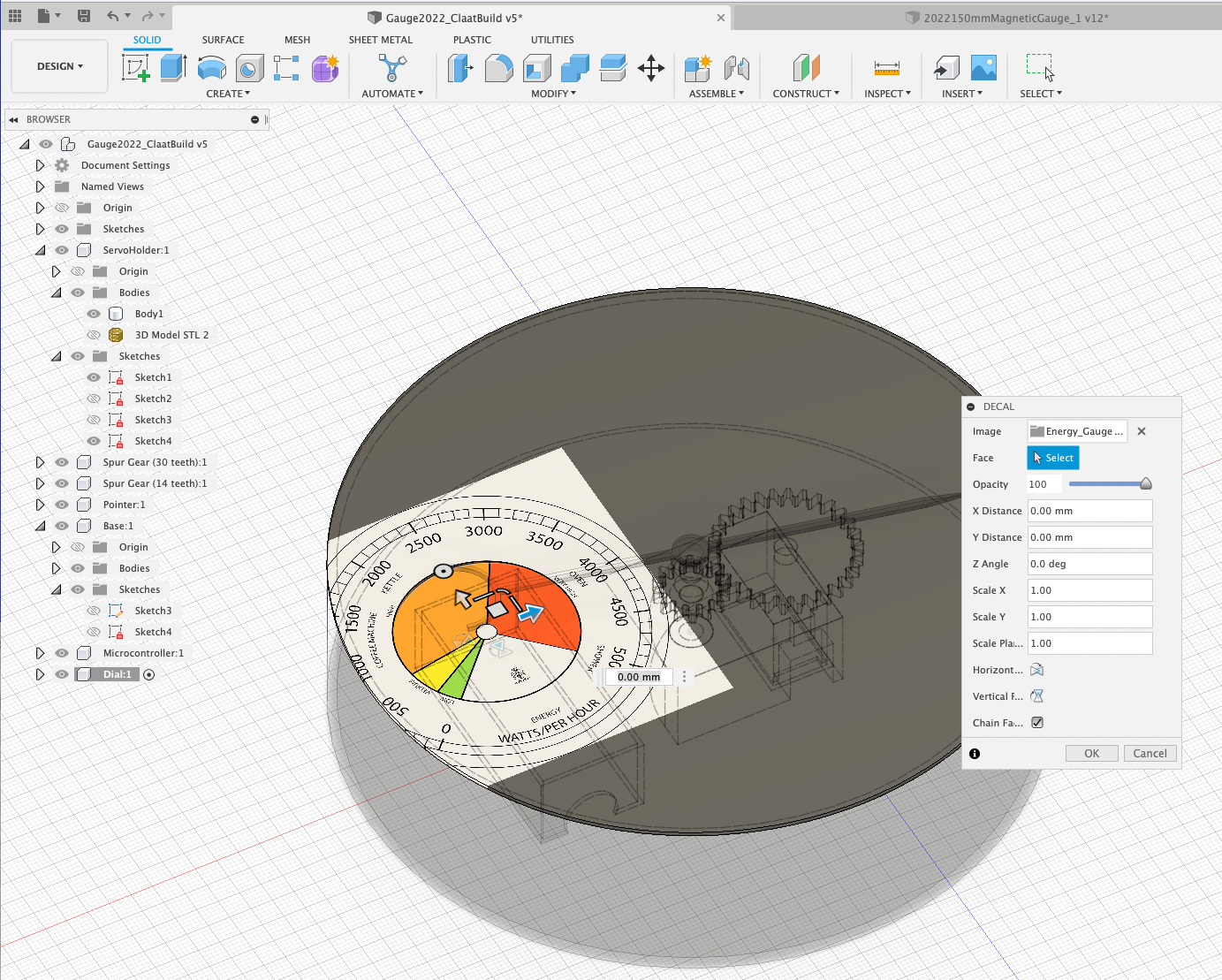
Move/Resize/Rotate until the image is centred and lines up with the face.
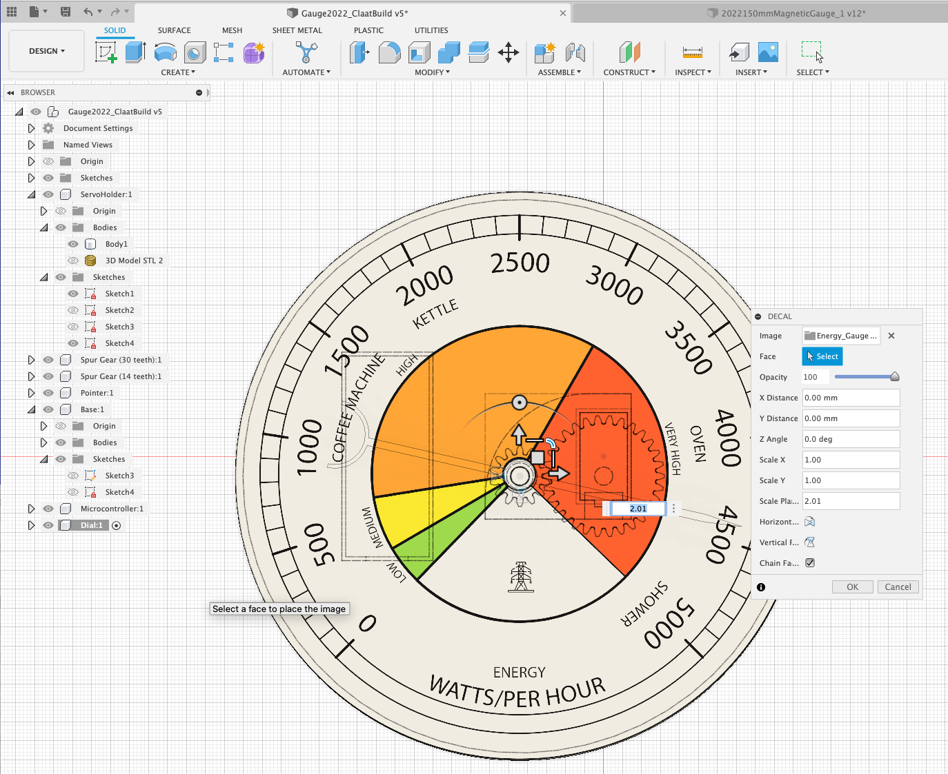
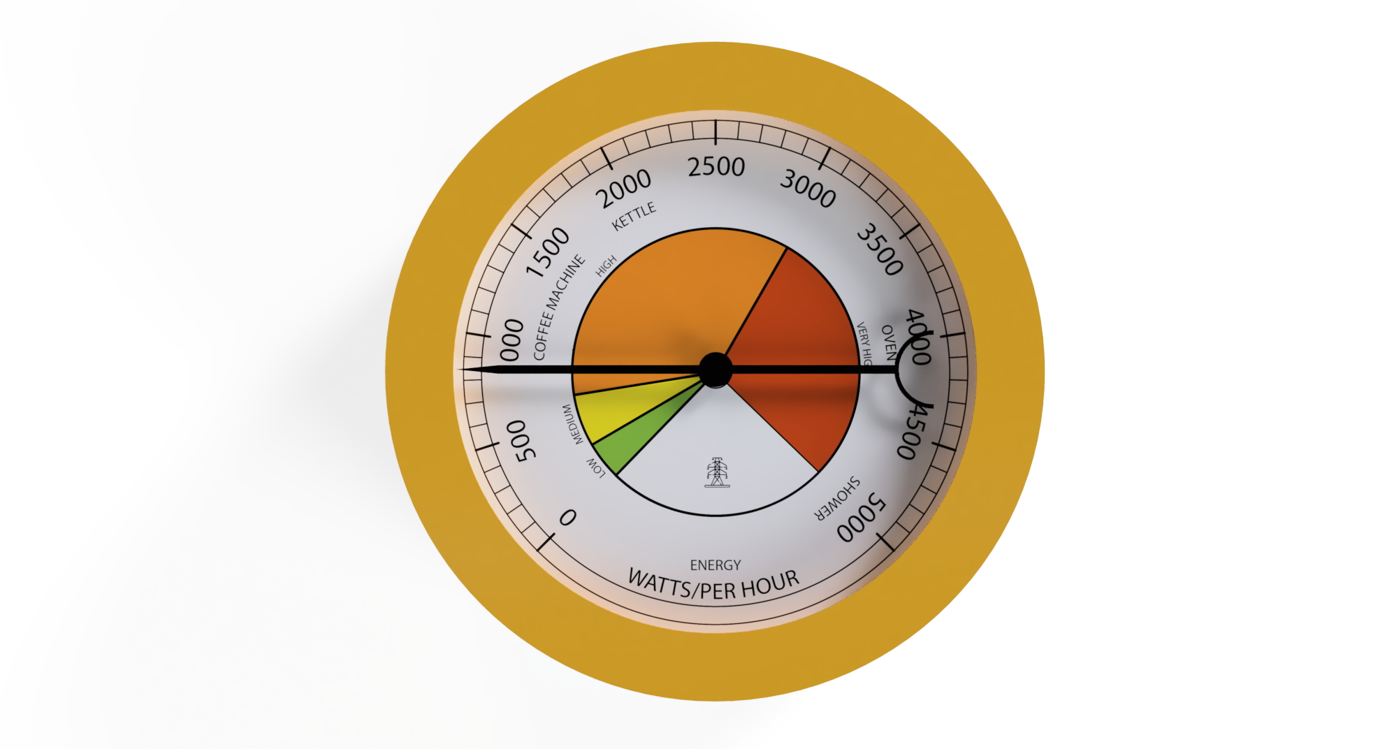
You now have the dial in place.
We now need to make two components to hold both the Dial and Acrylic disc in place. It should allow easy access to disassemble the Gauge, while also being hinge and glue free.
At this point the workshop forks - the latest version of the gauge (October 2023) uses a Screw Top Lid Method, where as the 2022 version uses a series of magnets to provide a ‘Snap on Cover'. Both methods allow the front dials to not only be held in place but also easily interchanged. We recommend carrying on with the Screw Top Lid Method, but have left the 2022, Magnets technique here for those interested...
Screw Top lids are useful for all sorts of enclosures and they are easy(ish) to make in Fusion 360, the only issue we need to be aware of is Fusion does not compensate for 3d printing tolerances, so if we print using the default sizes the lid will not screw together, we need to add a couple of offsets and then the technique can be used for any enclosure where a part can fit inside and be screwed shut.
First off we need the base to be wide enought to add the thread - this is simple, push/pull ‘q' the side of the base by an additional 5mm. This provides us with a thicker rim, allowing the thread to be modelled.
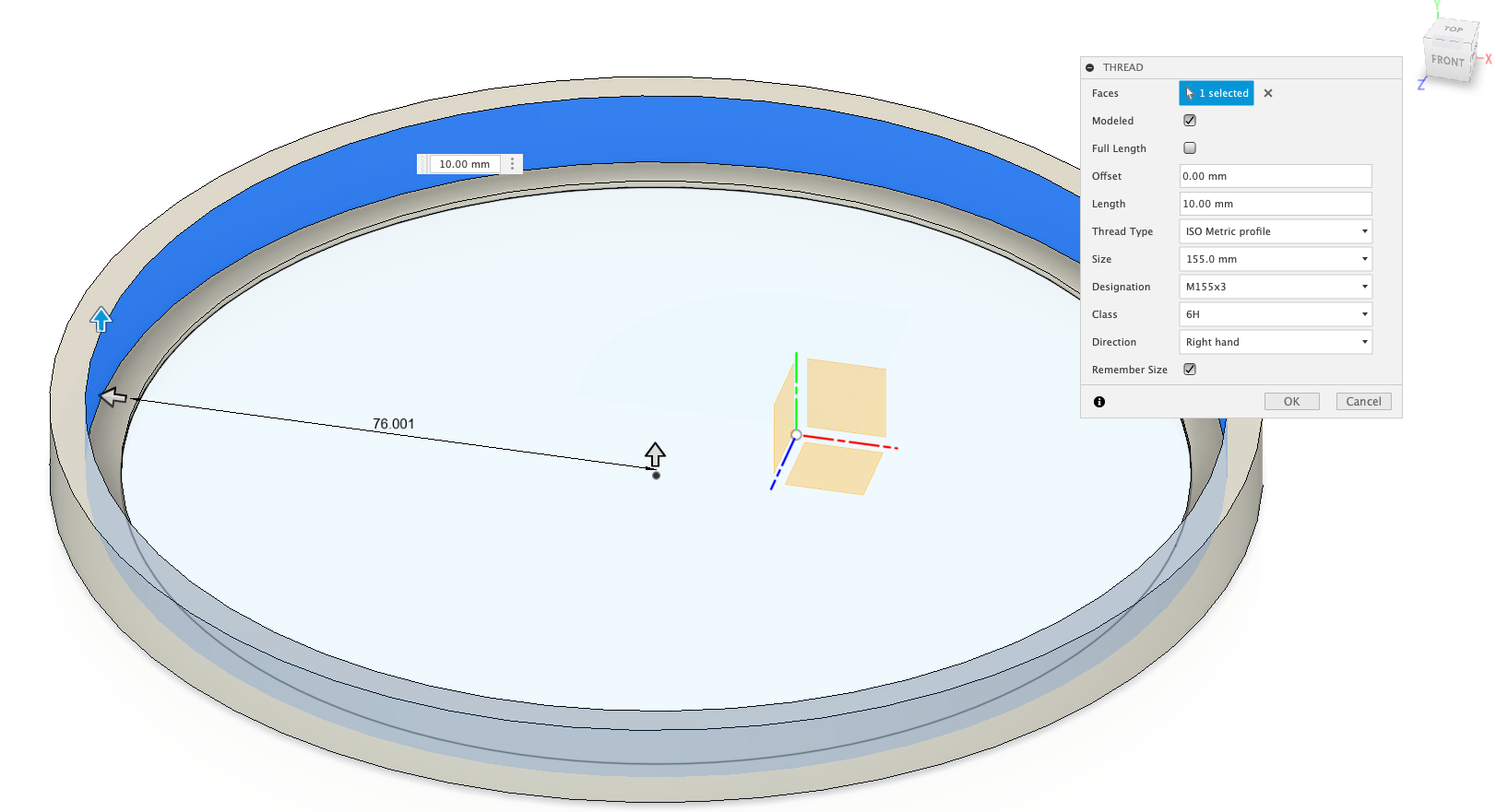
Threading is added to any round object using the Create -> Thread and then selecting the side of the object where you want the thread - in our case the outside of our base, so a lid can screw ontop.
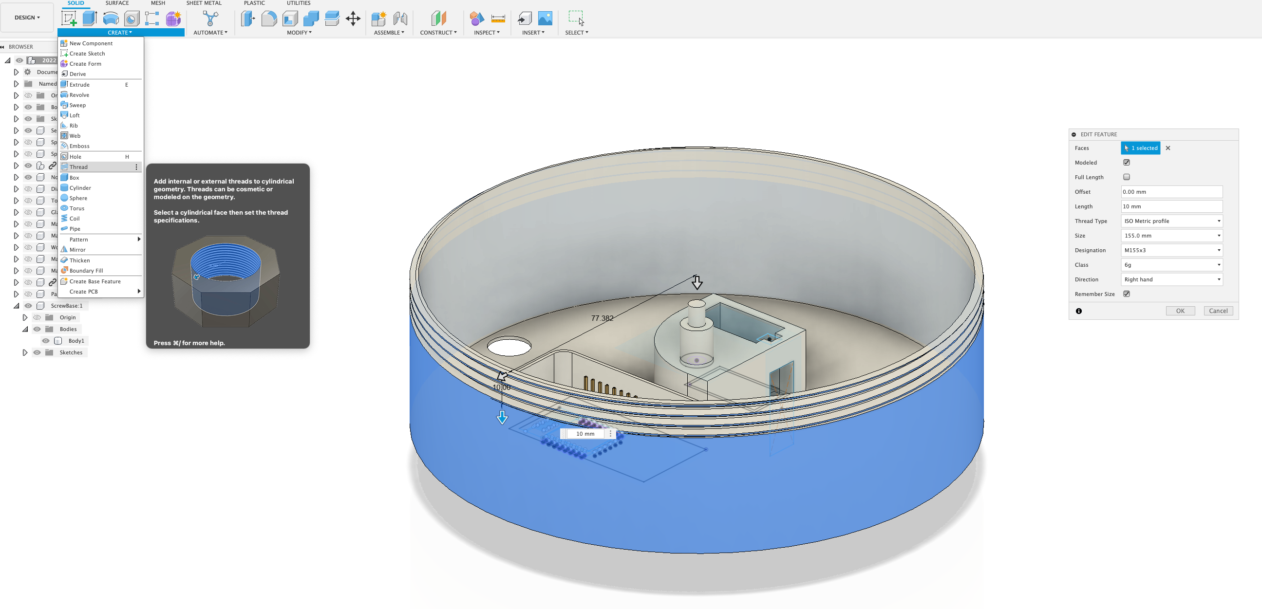
A pop up box will appear with a number of options, Fusion will automatically try to guess the best thread size - if it has not selected them automatically:
- Check
Modeled(to convert the thread in actual geometry) - Uncheck
Full Lenght - set the
Lenghtto 10mm (which allows a good size to match the lid, which we are going to make next) - set
Sizeto 155mm Designationto M155x3 - the x3 gives a mid size thread which is good for 3D printing.- check
Remember Size
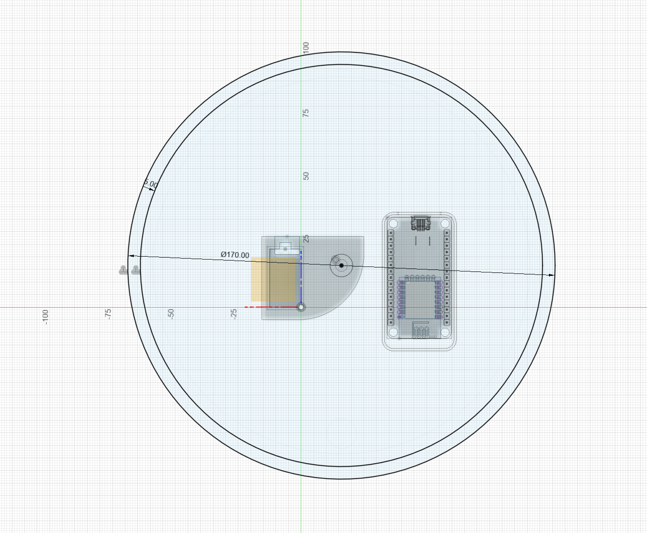
To make the lid we make the usual new component and start with a sketch, create a circle 170mm in size and offset by 5mm - this gives the same outcome as creating two circles - 160mm and 170mm, this is the same size of the base, with a 10mm width to allow for the size of the thread.
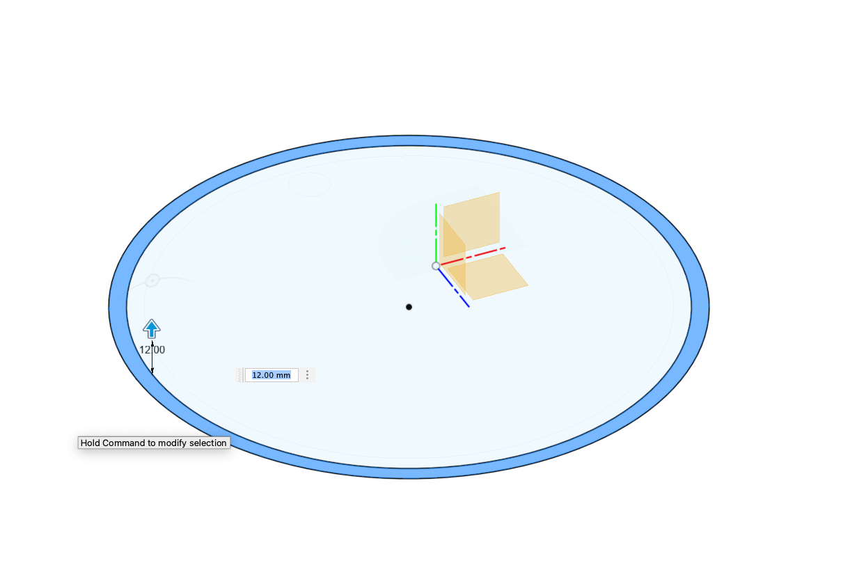
Extrude this up by 12mm - we will be putting in place a 10mm thread, so 12 mm allows enough space to work with.
Before we add in the thread, we want to add a rim, this will hold the perspex cover and give a visual framing of the gauge. To add a rim we are going to go to the bottom view and offset the inner ring by 5mm.
We then push/pull this by 1 mm to create the rim.
We are now ready to make the thread - using the thread drop down, click on the inner face and it will remember our last settings, automatically creating the thread. Again check that Modeled is ticked.
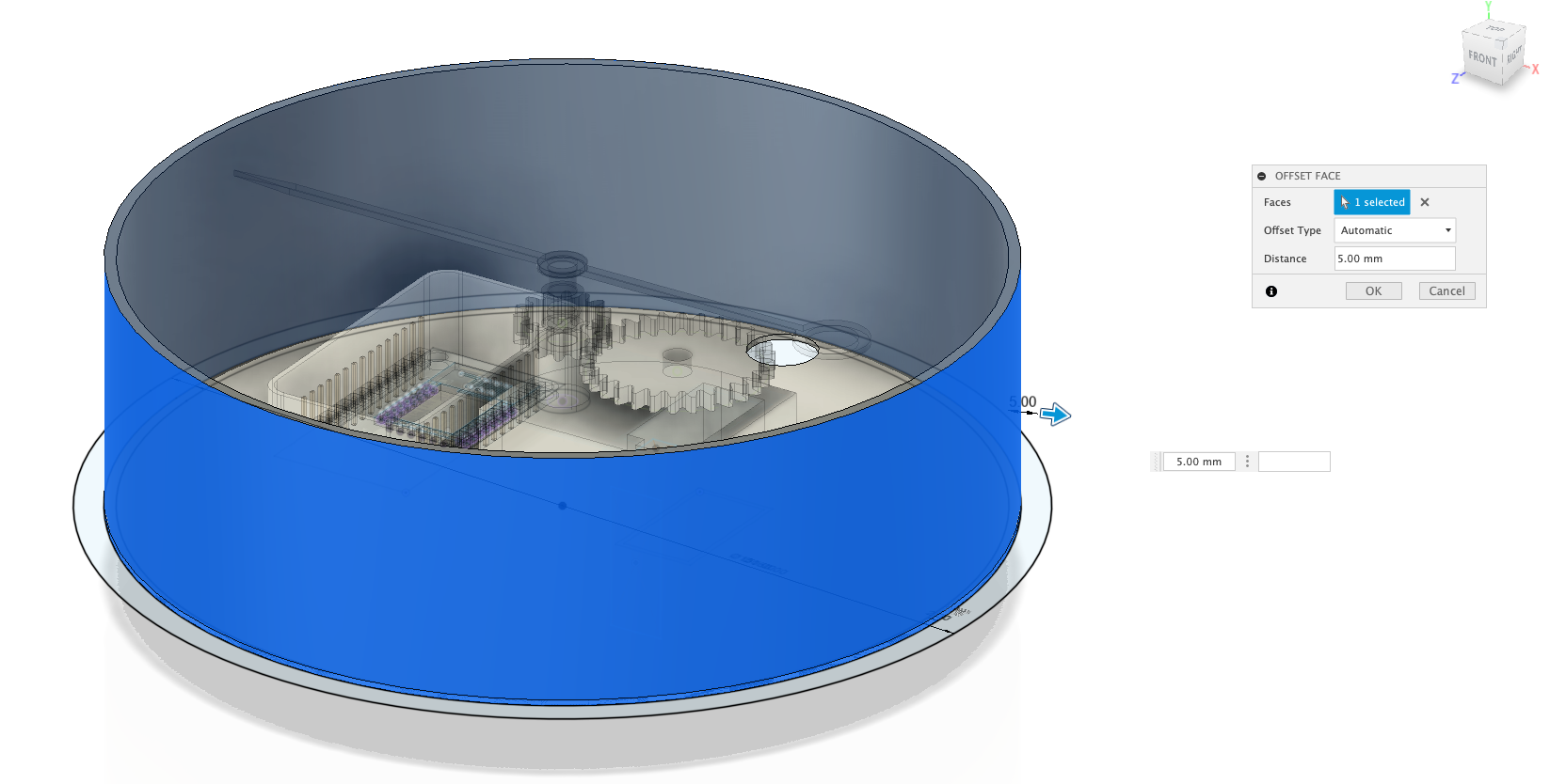
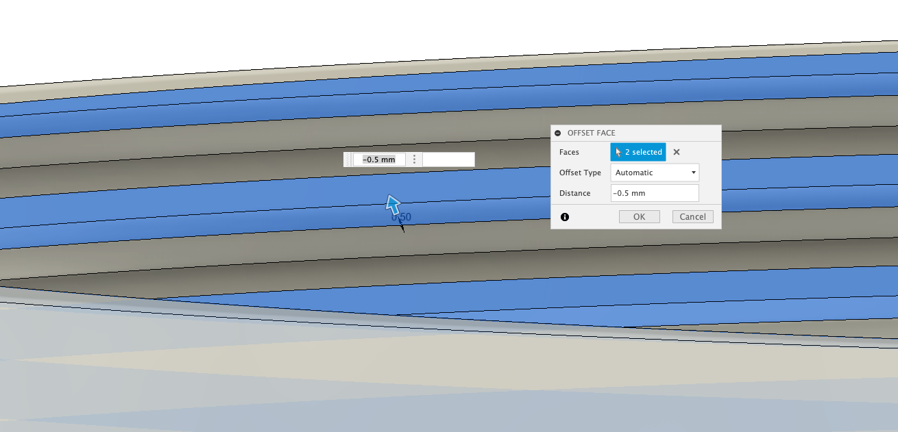
All we need to do now is to put in some offsets, to allow for 3D printing.
The offsets need to be on both sides of the thread - select either the top of bottom ring of the thread, hold shift and select the other and push pull ‘q' to set back 0.5mm.
Check the orinentation of your lid and rotate/move as needs be - you are now ready to add the final parts - the dial holder and then move onto the Tidying Up section.
The dial holder is needed as if you add in your 150mm dial to the gauge it will fall through, it simply needs a platform to sit on. To acheive this in the simplest way possibly we are going to add in three pillars for it to sit on.
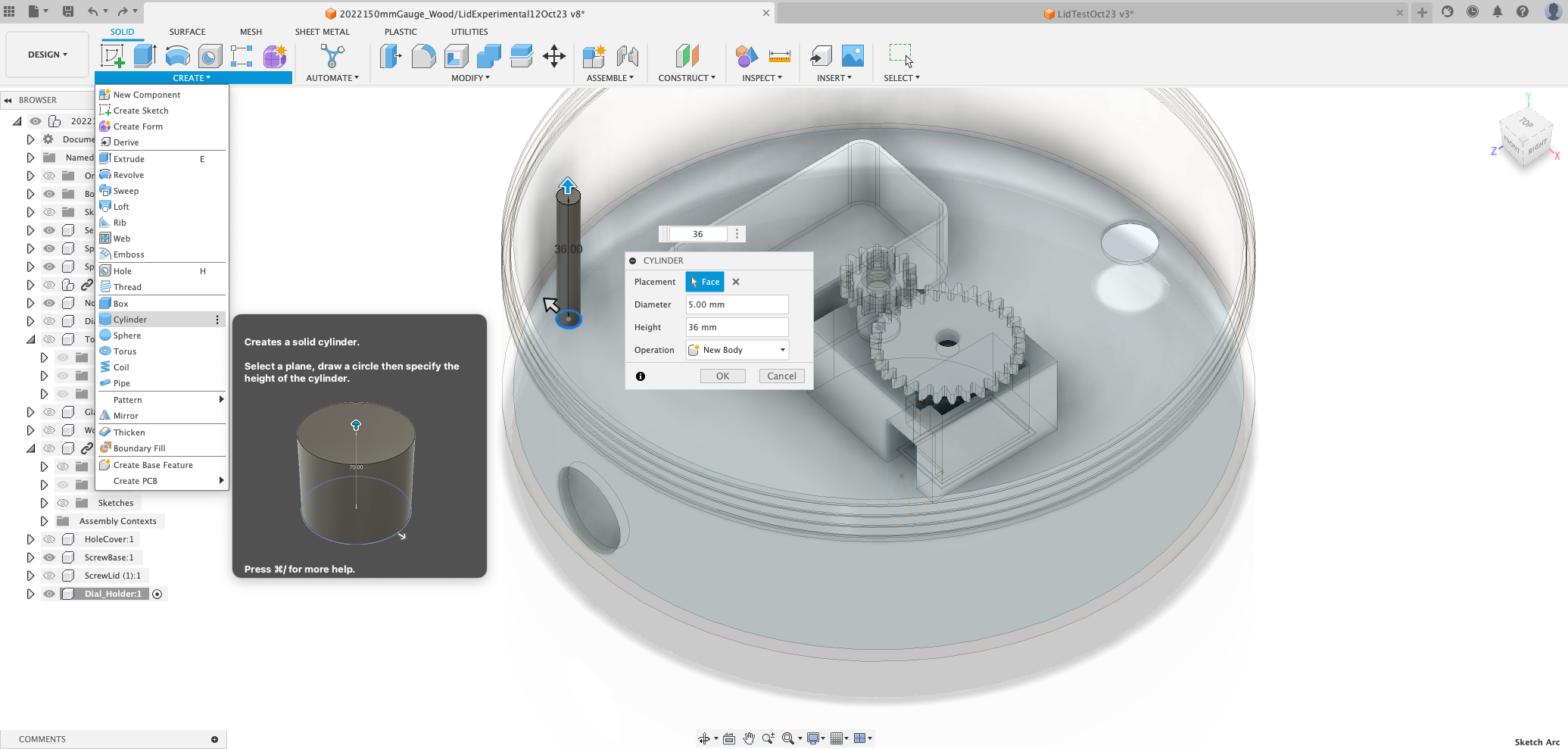
Dial Holder
Create your first pillar near the outer rim. As ever, first create a new component and name it something sensible - such as Pillar - using the Create, Cylinder Tool, clicking on the bottom face, make it 5mm and extrude 36mm. This is just above the gears, allowing the gears to move smoothly and the dial to sit above.
So the dial sits cleanly, we need three Pillars around the base, we can achive this by cloning our exisiting Pillar and using the Create Pattern Tool.
Go to ‘Create, Pattern, Circular Pattern' - this opens the Pattern tool, note that under this drop down you can also place objects along a path.
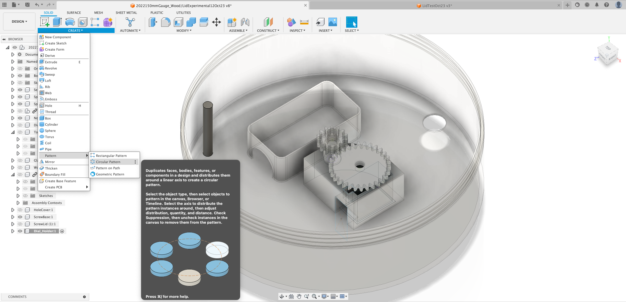
Select our Pillar and the click the Axis and click on the outside of the Gauge - this provides a circular path. You can now change the number of copies to make - we have used 4.
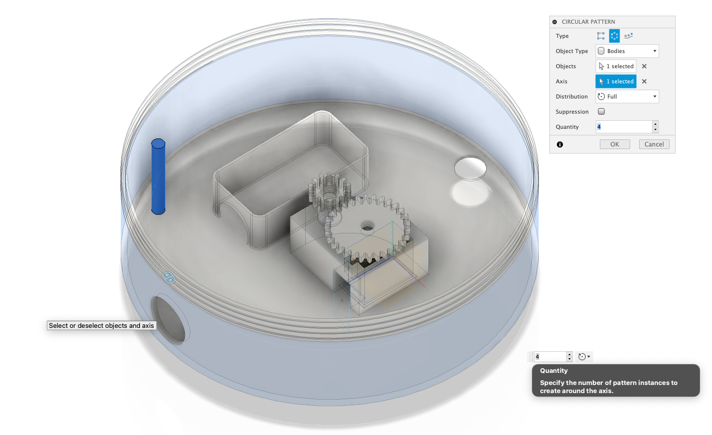
You should now have a series of Pillars on which the dial can sit.
One final check - if you bottom hole has disappeared, to allow the USB lead to feed into the gauge, add it back now, using the Hole tool - you should have a base similar to above.
Base Magnets
There are multiple ways magnets could be embedded into the base to create a magnetic snap with the acrylic holder. For this example we are going to design three round holders which extrude from the base - the design is there to experiment with.
We only need to make one new component, we can then simply copy it and place it on a circular path to complete the holder.
Create a ‘New Component' and call it ‘MagnetHolder', create a new sketch on the bottom of the base.
Draw a line from the centre up through the base - we are going to make this a ‘Construction Line' - Right Click on the Line and select Construction or, with the line selected, press X. This gives us a centre line to work from.
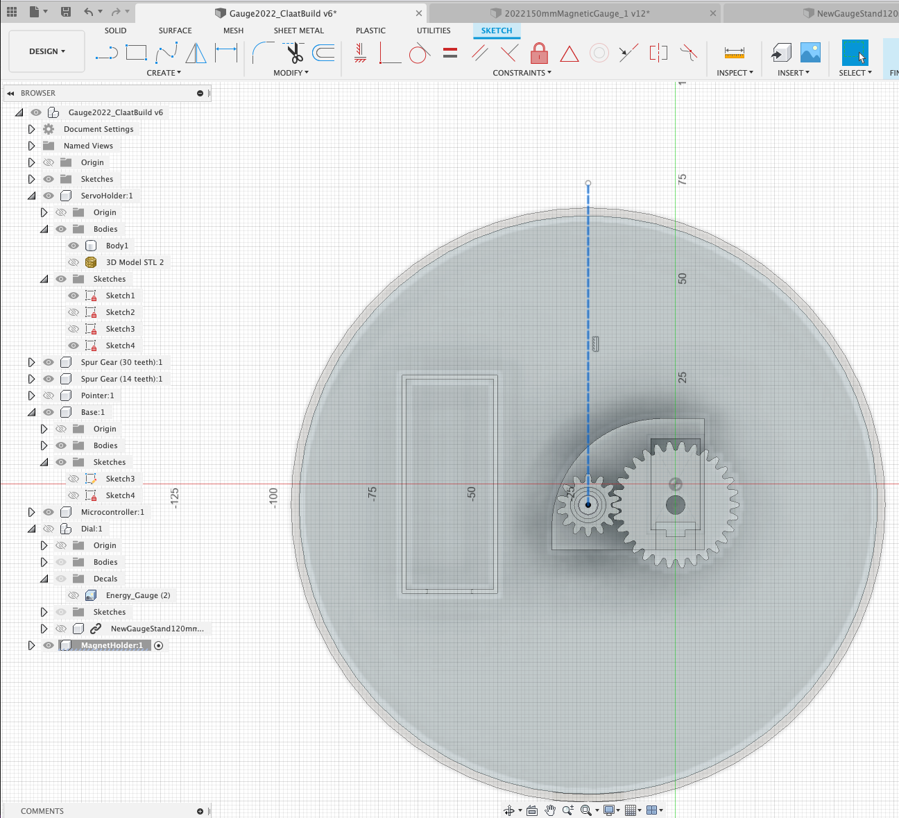
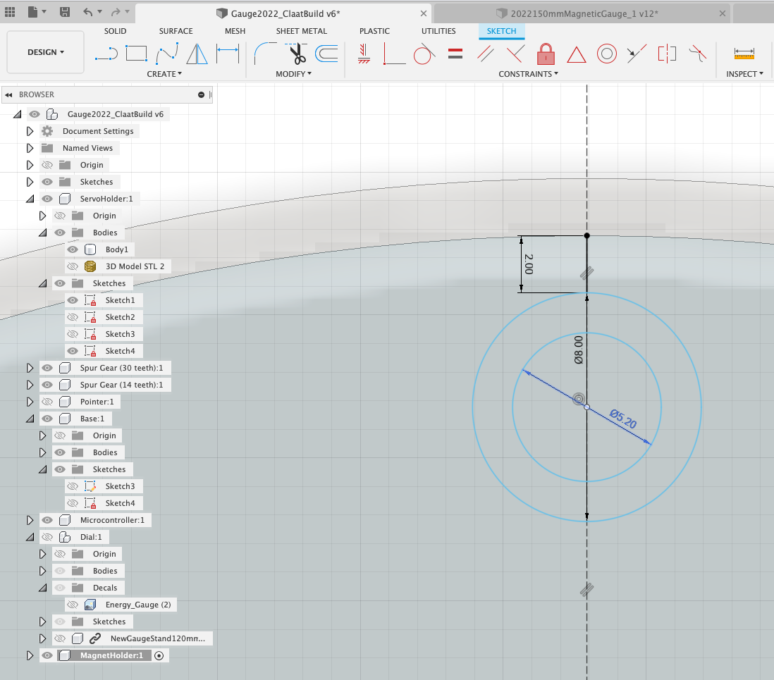
We want the Magnet Holder to be offset 2mm from the rim (so our NeoPixels can fit behind it). Create a line and draw it 2mm from the rim of the base, this is our marker to place our magnet holder.
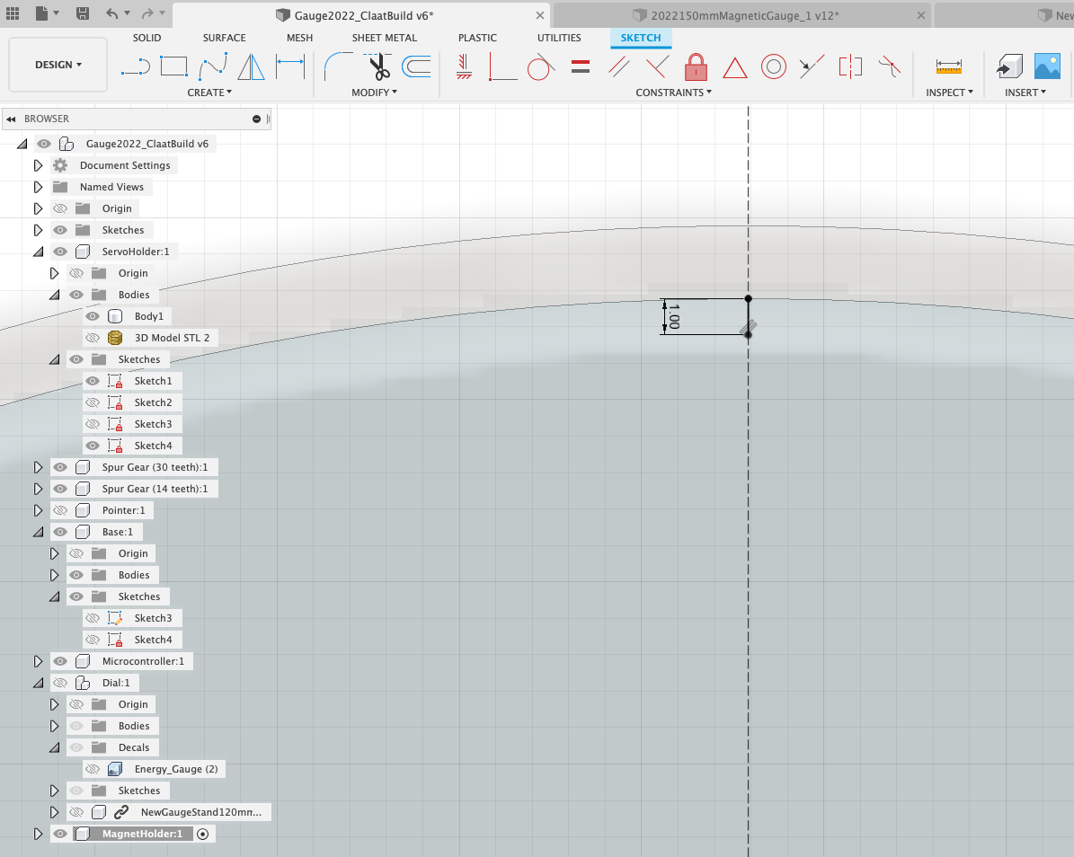
Create a ‘2 Point' Circle, 8mm and a Centre Point Circle 5.2mm in size - as shown below. Our Magnets are 5mm, the 5.2 circle provides a tight fit.
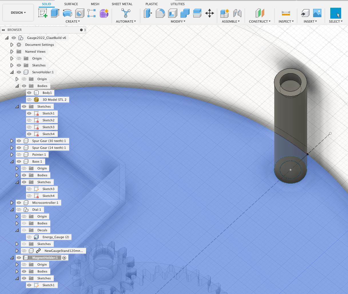
We now need to simple extrude the inner ring by 37mm (to allow the Magnet to sit flush) and the outer rim by 40mm (the top of the base).
All we need to do now is copy the component around the base - using ‘Create' ‘Pattern' ‘Circular Pattern'.
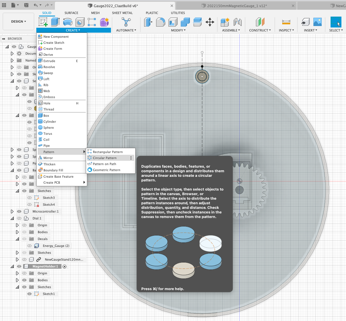
Our object type is a ‘Component', The ‘Axis' is the rim of the base and we are creating 3 copies. Patterns can also be ‘Paths' to quickly clone components in a model.
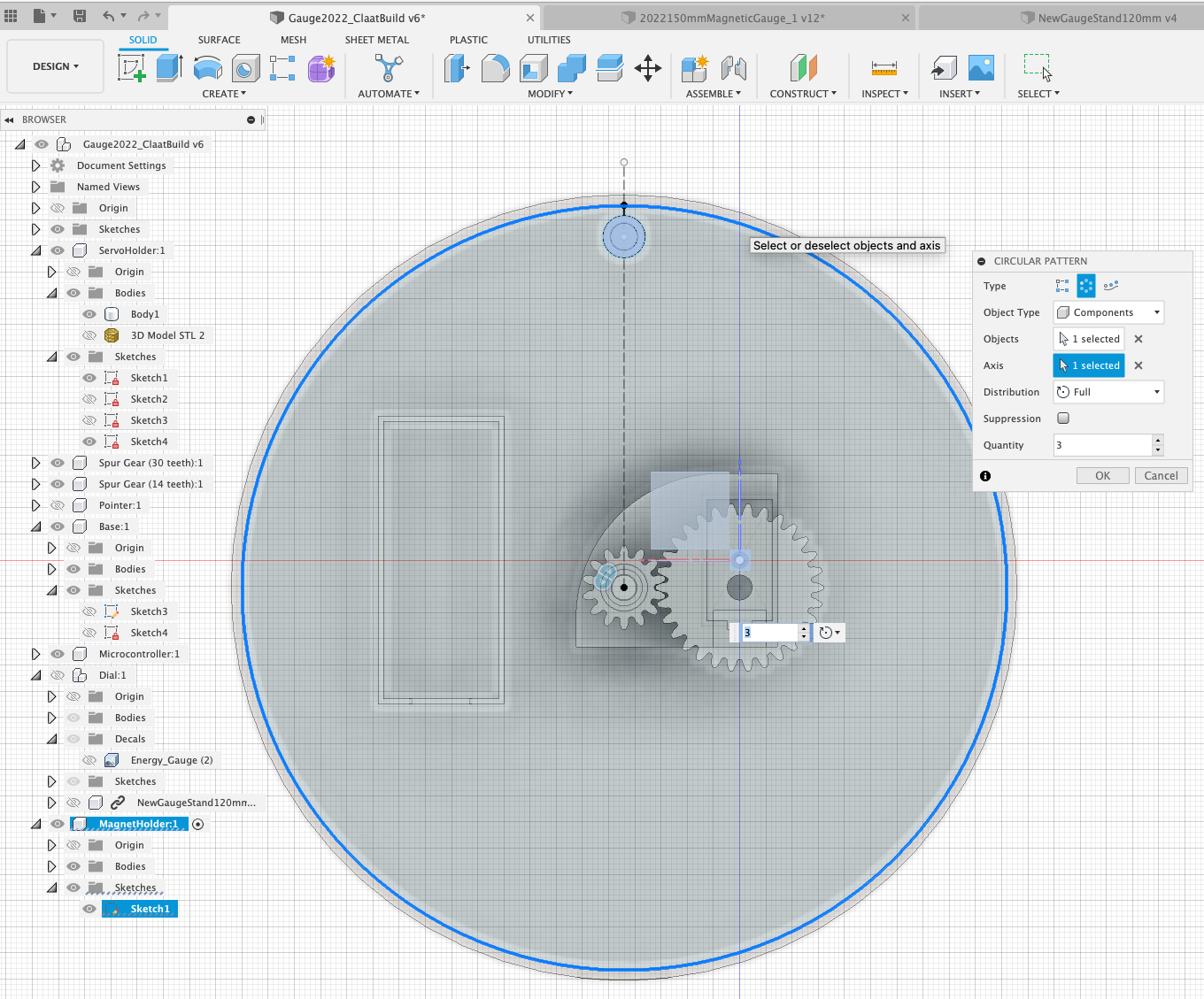
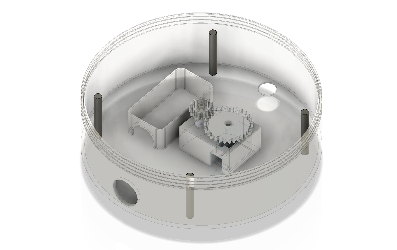
Your base is now complete.
Acrylic Holder
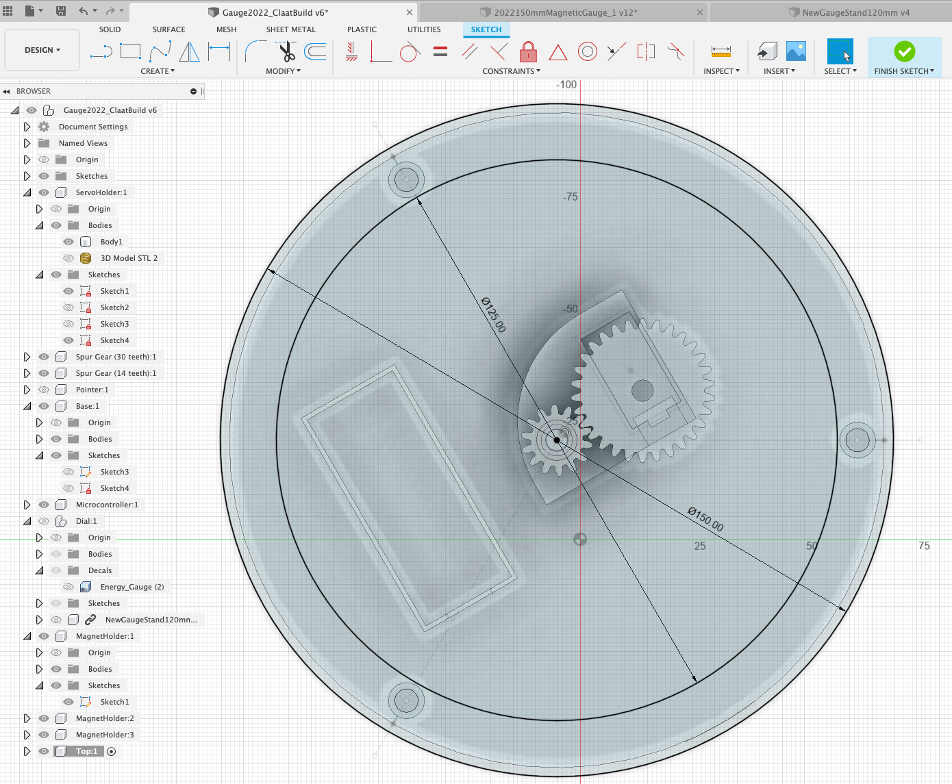
We now need a similar component for the Acrylic - which needs to sit above the dial with enough space for the Pointer to freely rotate and to snap onto the magnets.
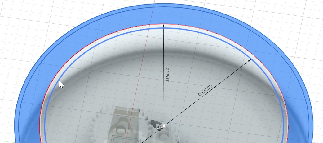
Make sure the main parent is selected and create a ‘New Component', call it ‘Top'. Create a Sketch and 3 Centre Point Circles - one 150mm, another at 125mm and a final one at 120mm - these create the space to hold the magnets and a rim to hold the Acrylic.
Extrude the outer ring by 10mm (you might have 1 additional external ring created by the projection of the main body of the gauge) and the inner ring by 1mm. All we need do now is move the Top in place and match up the hole for the magnets.
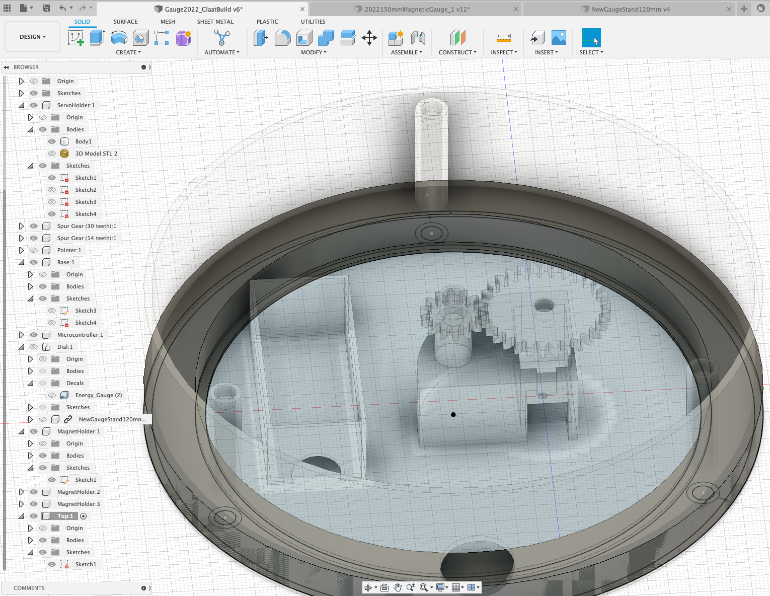
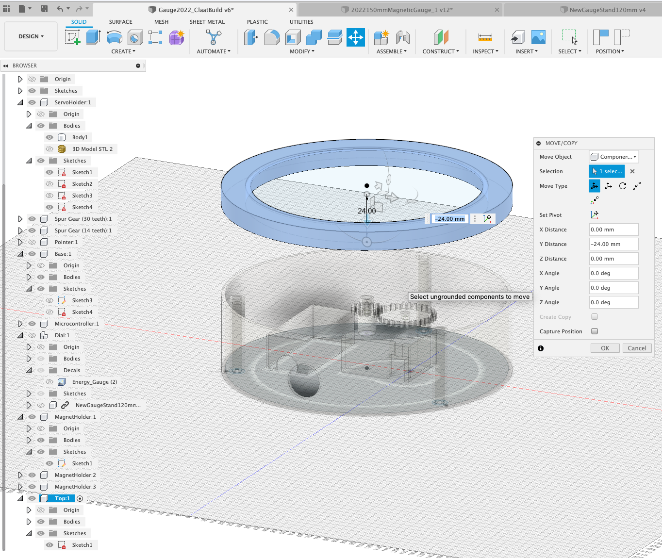
Rotate the Top 180 degrees (if required so the thin rim it at the top) and move it up above the base so we can work on the bottom and the final part - the holes for the magnets. This is simply a new sketch and projecting our existing holders.
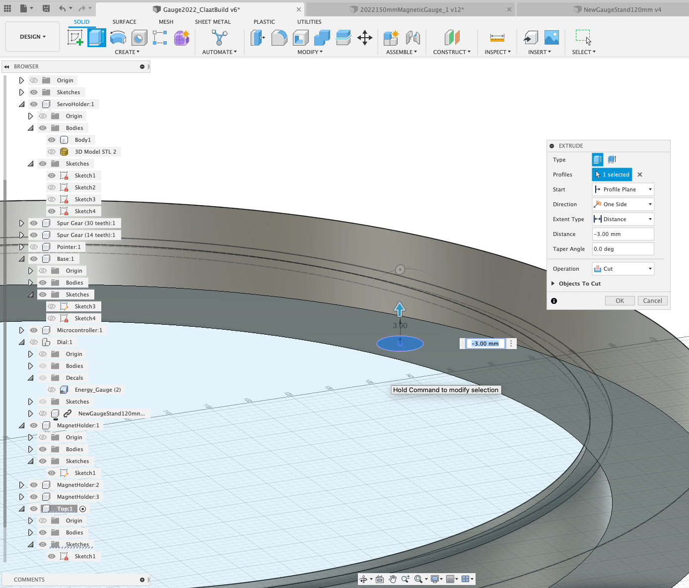
Create a ‘New Sketch' on the bottom of the Top component and ‘Create' ‘Project' - Select our existing Magnet Holes to transfer them to out Sketch.
Now extrude these three circles back, inside the Top component by -3mm
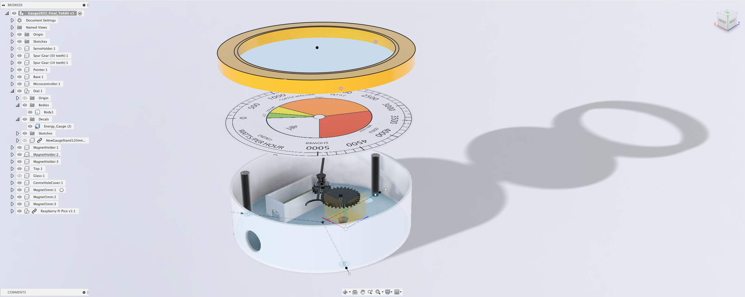
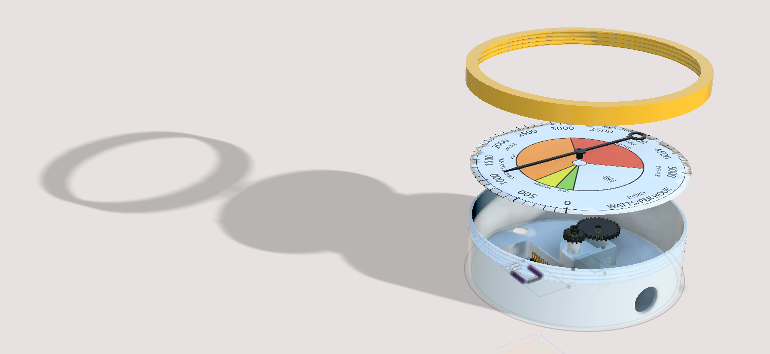
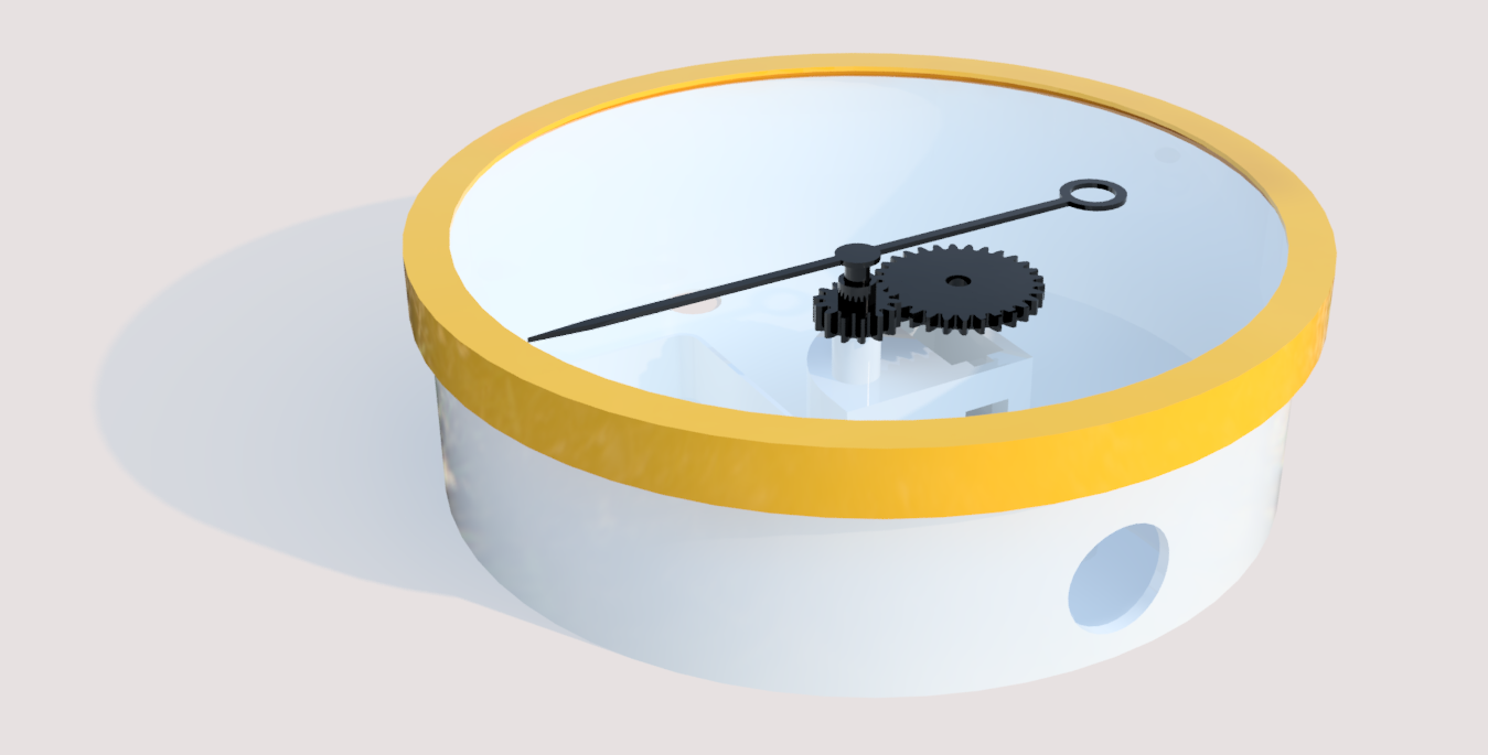
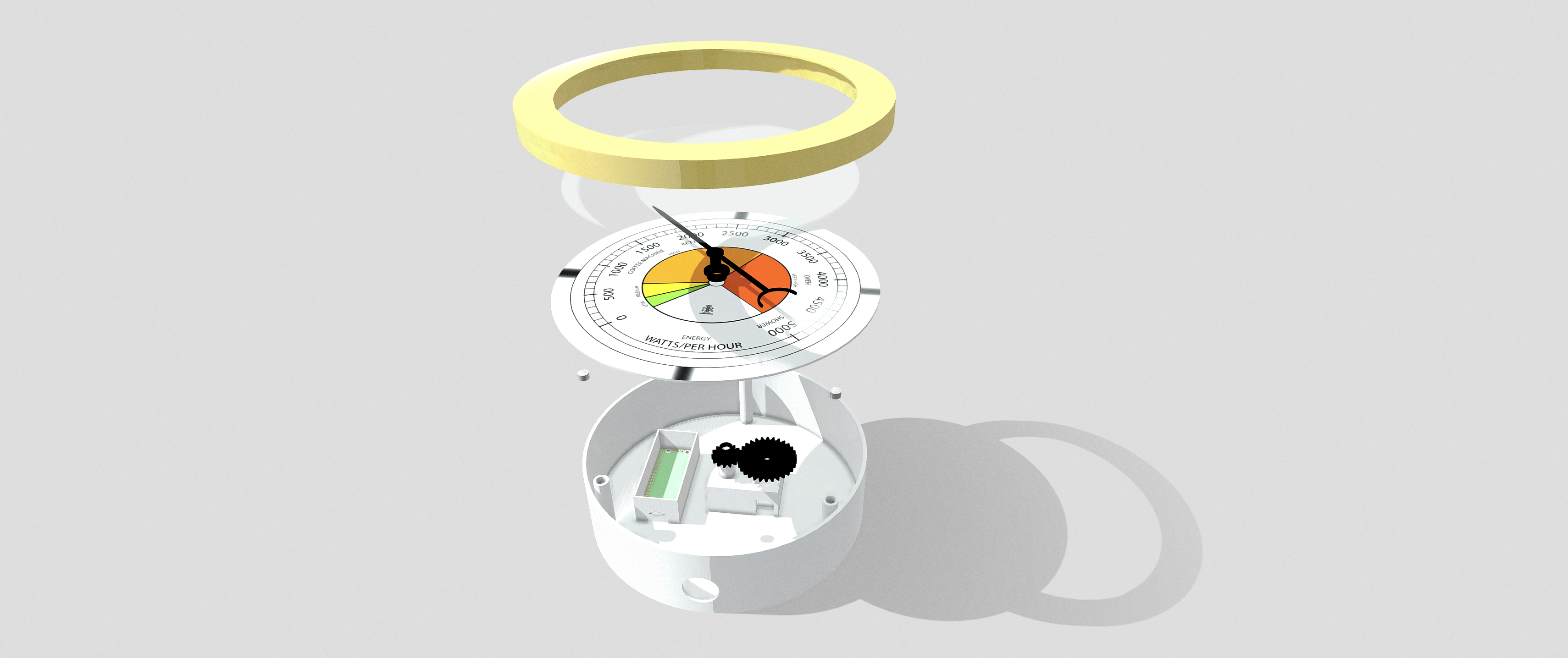
Done! You can now move the Top into place for a render/export and to 3D print each of the components.
Now the main gauge is in place, you can add a couple of additions to improve both the render and the overall object.
Glass
The first is to add ‘Glass' this is simple a 125mm circle extruded to 1mm and lined up above the pointer. In the ‘Render' settings search for Clear Glass. We need the glass in place for using the model in both Blender and Augmented Reality.
Centre Hole Cover
The Dial is physically made using ‘Paper' - Paper dials are difficult to get clean centre holes punched, as such a small Centre Cover is useful to tidy up the final model:
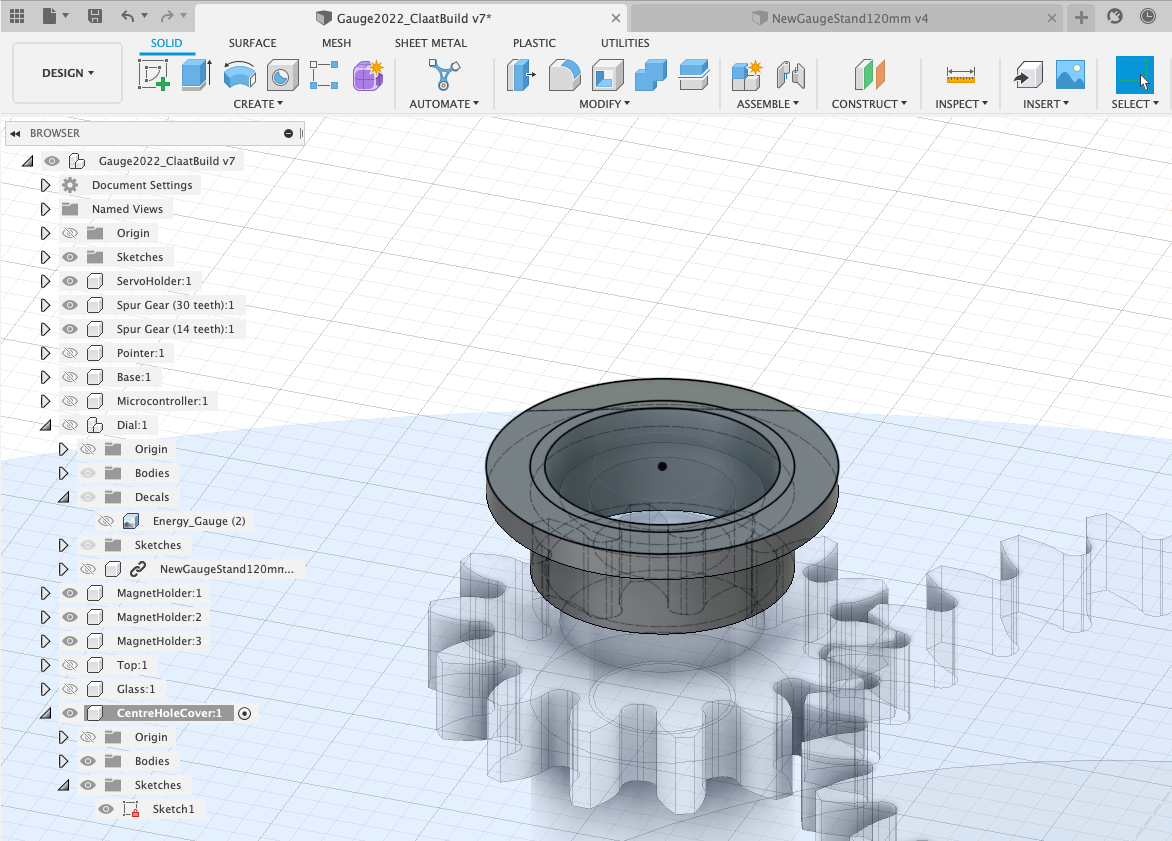
Complete - Well Done !
Fusion exports in a variety of formats - .fbx is arguably the most flexible as it allows import into almost all other packages while maintaining its hierarchy. All files are exported via the cloud and take longer than they would locally.
To export a file, simply FileExportFBX. The export in Fusion is however slightly underwhelming, no textures or animations export with the file.
We solve the lack of animation and texture export in the follow up lecture by importing the model into Blender, SketchFab and Unity.
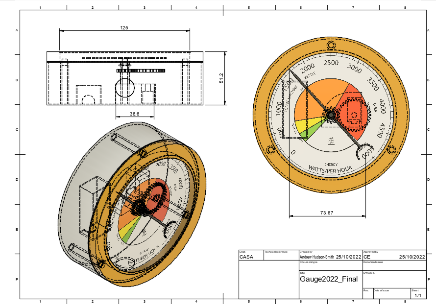
Technical Drawings are a key part of Fusion, they update dynamically on any file changes and provide a key way to provide size and location details of your model.
To create a technical drawing simply go to FileNew DrawingFrom Design note the options on sizing etc. This process opens a new window and interface.
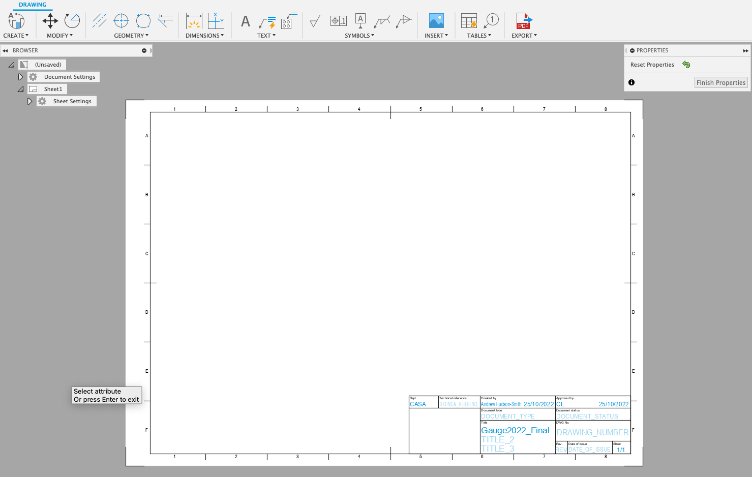
Views are added by creating and dragging (which is slightly counter intuitive at first). Click Create, selects a Base Line view and then click on the main canvas. You can change the View/Style/Scale etc in the dialog box - wireframe works well for technical drawings.
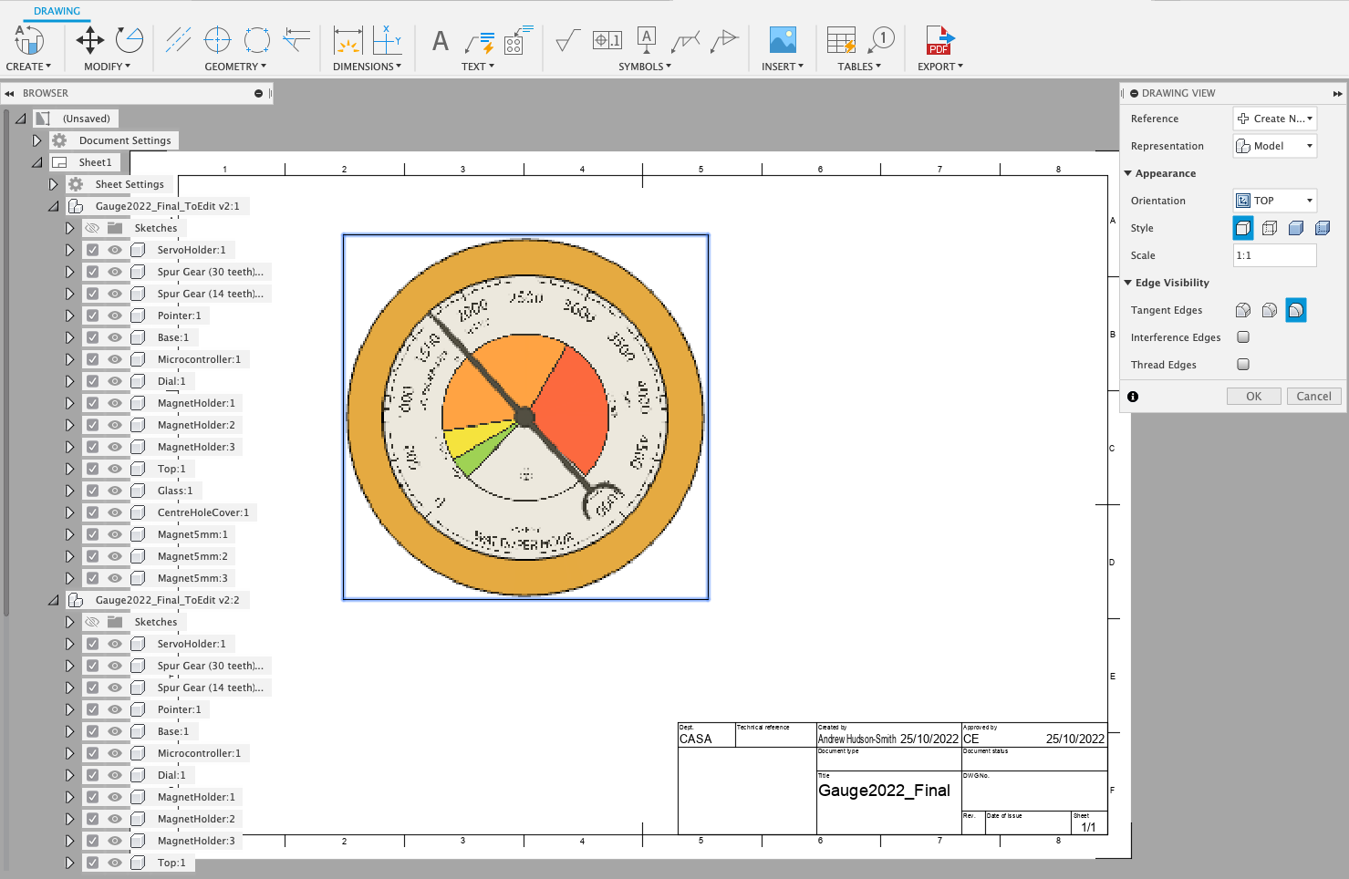
The interface is quite self explanatory - Dimensions allows you to click and drag on objects to show the dimensions etc.
You can click and drag new views to add top/side elevations etc - below details an example using the Gauge:
Your Physical and Digital versions of the Gauge are now complete.
The next steps with the Digital Version are to export and make the pointer move accordingly to a data input for use in both Augmented and Virtual Reality. We run though this in a following workshop.
For the physical version it is to 3D print, install and wire up the components and edit the Arduino Sketch/Micropython for the data feed of your choice.
Our code can be found on GitHub
Well done - you now know all the required parts of Fusion 360 to design, render, animate, export and make almost anything.