Dowload and install the Arduino IDE
This workshop will enable you to set up an Arduino LoRa board (The Things Uno) to upload data from some simple sensors to the Things Network over LoRaWAN (a low power, long range wireless protocol).
You will make use of the DHT22 Humidity and Temperature (digital) sensor as well as a simple light dependent resistor (an analog sensor) to monitor Lux levels.
First launch the Arduino IDE. To familiarise yourself with the Arduino platform you will first load a basic blink sketch from the examples that are distributed with the Arduino IDE.
Load the following sketch:File -> Examples -> Basics -> Blink
Ensure board set to Arduino Leonardo:Tool -> Boards -> BoardManager -> Arduino Leonardo
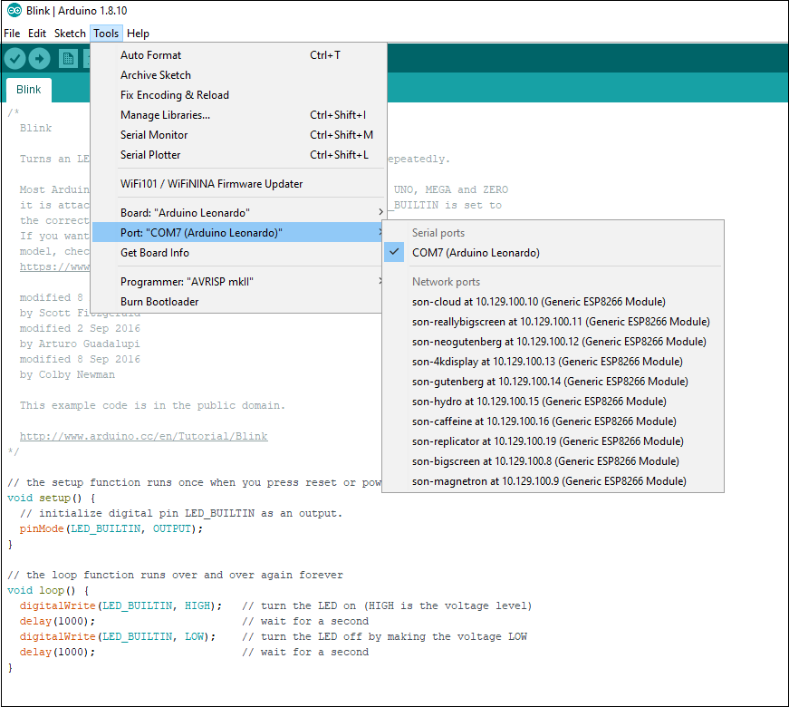
Ensure the correct port for the Arduino Leonardo has been selected:Tools -> Port:...
as shown in the screenshot below for Windows:
and for Mac:
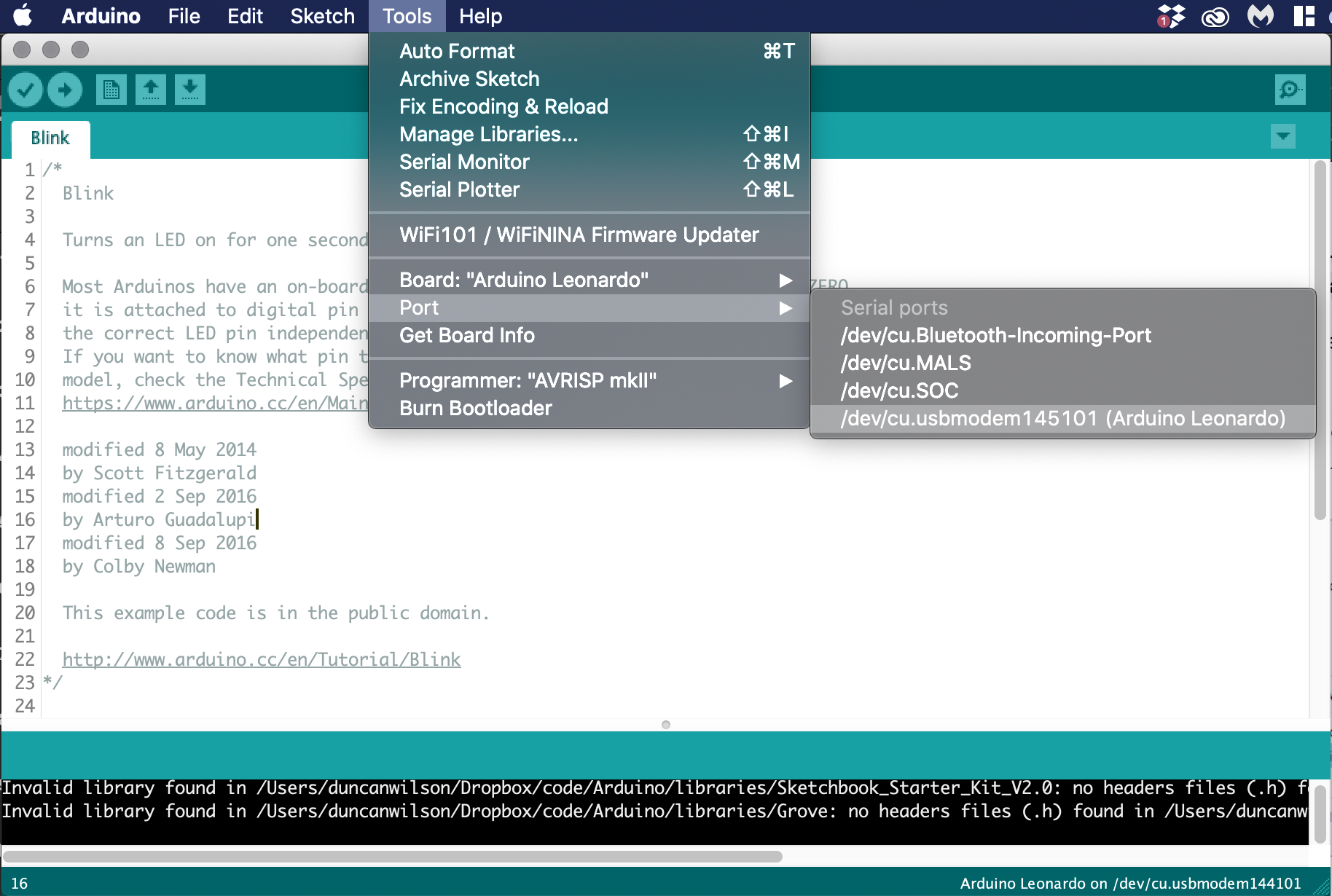
Note that the your board may connect on a different COM port to the one shown in the screenshot above (COM7).
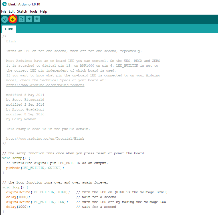
Now upload the sketch using the upload button (as shown below)
If you look at the Leornardo board you should see the built in LED blinking every second.
Wire up the circuit as shown in the diagram below:
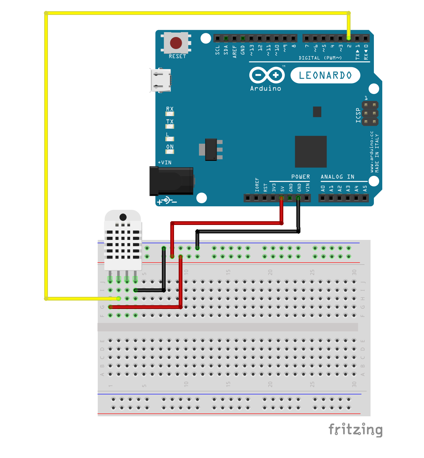
The DHT 22 is a combined Humidity and Temperature sensor producing a digital output. To read the DHT sensor from an Arduino sketch you need to include the DHT library.
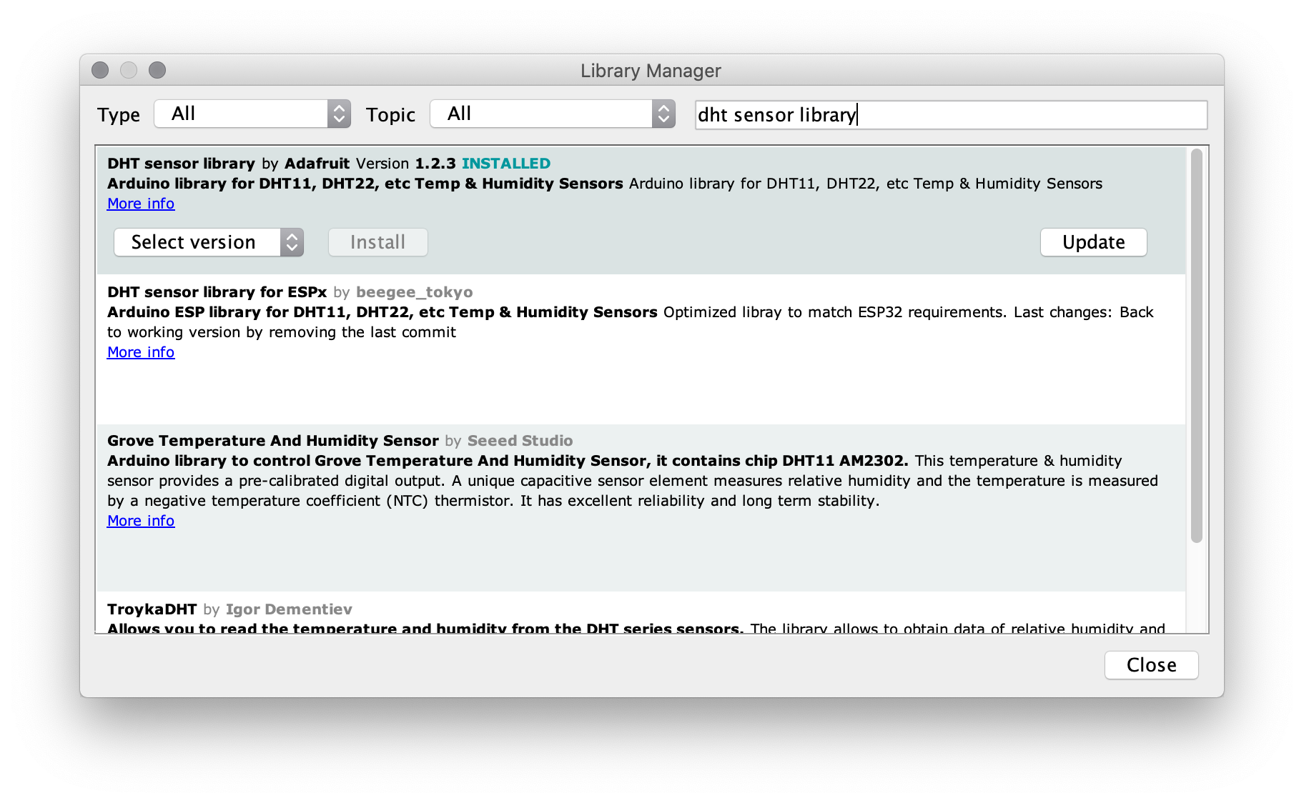
From the Arduino IDE load the Library Manager:Sketch -> Include library -> Manage Libraries
Enter ‘DHT sensor library' in the search box and install the DHT sensor library by Adafruit.
When the library has installed create a new sketch. From the menu click:File -> New
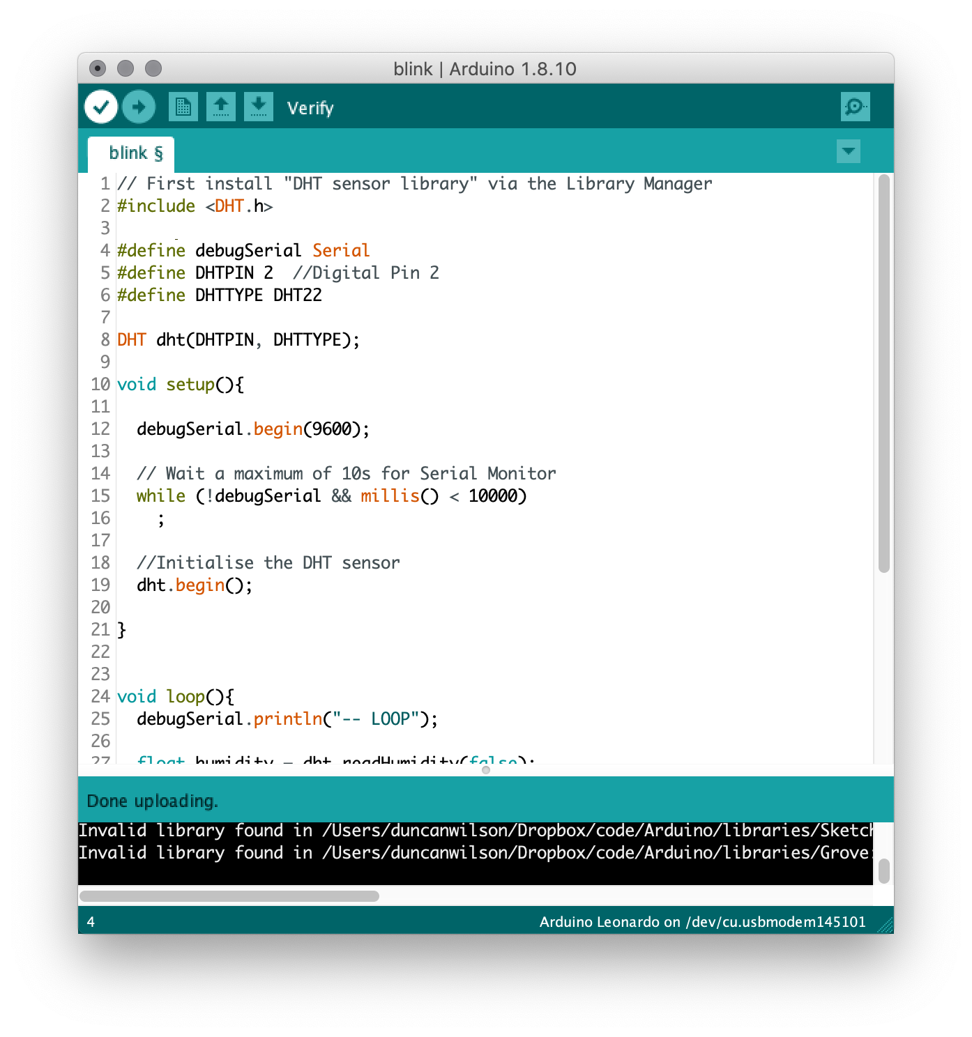
Enter the following code in the sketch
// First install "DHT sensor library" via the Library Manager
#include <DHT.h>

#define debugSerial Serial
#define DHTPIN 2  //Digital Pin 2
#define DHTTYPE DHT22

DHT dht(DHTPIN, DHTTYPE);

void setup(){

  debugSerial.begin(9600);

  // Wait a maximum of 10s for Serial Monitor
  while (!debugSerial && millis() < 10000)
    ;

  //Initialise the DHT sensor
  dht.begin();

}


void loop(){
  debugSerial.println("-- LOOP");

  float humidity = dht.readHumidity(false);

  // false: Celsius (default)
  // true: Farenheit
  float temperature = dht.readTemperature(false);

  debugSerial.print("Temperature: ");
  debugSerial.println(temperature);
  debugSerial.print("Humidity: ");
  debugSerial.println(humidity);

  delay(20000);
}
Check the code has been entered correctly by compiling the code (click the tick at top left - see below)
If you see a message ‘Done compiling' it indicates the code has compiled sucessfully. If you are having problems getting your code to compile, ask for help from one of the tutors.
Once you have the code compiling sucessfully you can upload the sketch to the Arduino Things Uno board. Now open the Serial Monitor:Tools -> Serial Monitor
You should be able to see the values for humidity and temperature printed in the debug output.
Save the sketch as sense-and-sensing-lab-1 e.g. File -> Save As.
You are now going to add a new sensor to the circuit. A light dependent resistor (LDR) is a analog sensor whose resistance varies with the intensity of light falling on its surface. LDRs are constructed from a semiconductor material, whose resistance falls as light intensity increases.
Add the LDR to your circuit using the diagram below as a guide: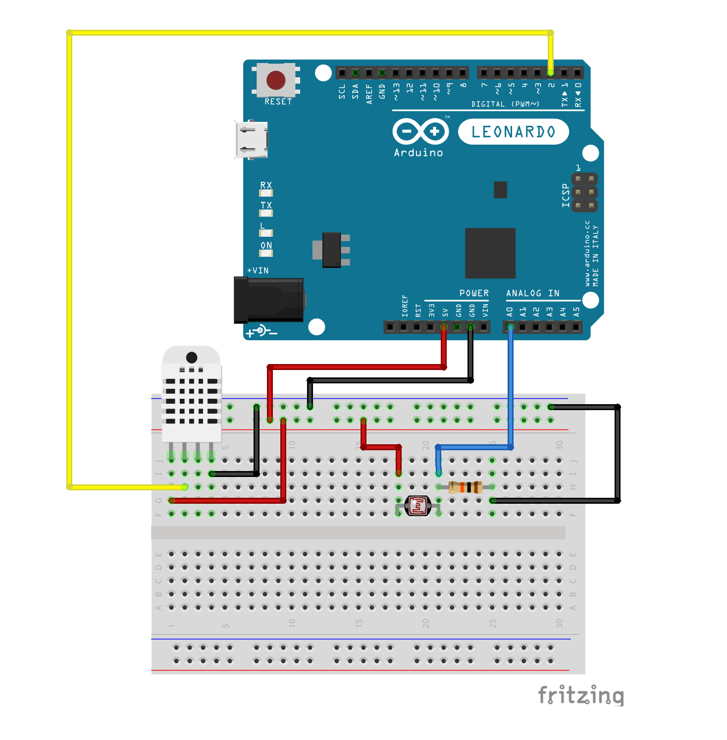
One terminal of the LDR is connected to 5V, while the other terminal is connected to a 10 kilo Ohm resistor. The other terminal of the resistor is connected to Ground. You will use the Analog Input A0 of the Arduino to monitor the voltage at the junction of the LDR and the 10 kilo Ohm resistor.
Now return to the Arduino IDE and the sketch you created earlier.
At the top of the sketch beneath the line #define DHTTYPE DHT22 add a new line as follows:
#define lightPin A0
Now in loop() beneath the line debugSerial.println("-- LOOP"); add the following:
int ldr = analogRead(lightPin);
debugSerial.print("ldr value: ");
debugSerial.println(ldr);
Compile and upload the sketch as before and open the Serial Terminal to view the debug output.
By default the analogRead() function returns a 10 bit integer value, between 0 and 1023, where 0 represents 0 Volts and 1023 represents the supply voltage, in this case 5.0 Volts.
To convert the ldr variable so that it actually reads in Volts we need to change the line int ldr = analogRead(lightPin); to the following:
float ldr = 5.0*analogRead(lightPin)/1024;
Your sketch should now look like this:
// First install "DHT sensor library" via the Library Manager
#include <DHT.h>

#define debugSerial Serial
#define DHTPIN 2  //Digital Pin 2
#define DHTTYPE DHT22
#define lightPin A0

DHT dht(DHTPIN, DHTTYPE);

void setup(){

  debugSerial.begin(9600);

  // Wait a maximum of 10s for Serial Monitor
  while (!debugSerial && millis() < 10000)
    ;

  //Initialise the DHT sensor
  dht.begin();

}


void loop(){
  debugSerial.println("-- LOOP");

  float ldr = 5.0*analogRead(lightPin)/1024;
  debugSerial.print("ldr value: ");
  debugSerial.println(ldr);

  float humidity = dht.readHumidity(false);

  // false: Celsius (default)
  // true: Farenheit
  float temperature = dht.readTemperature(false);


  debugSerial.print("Temperature: ");
  debugSerial.println(temperature);
  debugSerial.print("Humidity: ");
  debugSerial.println(humidity);

  delay(20000);
}
Once again compile and upload the sketch as before and open the Serial Terminal to view the debug output. Try placing a finger over the surface of the LDR - what happens to the ldr value?
Save the sketch using File -> Save
Currently the Arduino is measuring the voltage at the junction of the LDR and 10 kiloOhm resistor via the analog pin A0. This is not a very useful metric. However, we can use this voltage to estimate the instantaneous resistance of the LDR. For a voltage divider circuit using a 10 kiloOhm resistor in series with the LDR and a supply voltage of 5 Volts the resistance of the LDR is given by:
Rldr = 50/V - 10
where V is the voltage measured at the analog pin. Return to your sketch and in the loop() code, below the line float ldr = 5.0*analogRead(lightPin)/1024; add the following code:
  float Rldr = 50/ldr - 10;
  debugSerial.print("LDR resistance (kOhms): ");
  debugSerial.println(Rldr);
Once again compile and upload the sketch as before and open the Serial Terminal to view the debug output. Try placing a finger over the surface of the LDR - what happens to the value of the resistance of the LDR?
Save the sketch as before.
From the data sheet for the Light Dependent Resistor (LDR) we can make order of magnitide estimate for the resisitance of the Light Dependent Resistor, Rldr at given light levels e.g.
Rldr = 10 kiloOhms at 0 Lux
Rldr = 1 kiloOhms at 100 Lux
Using the above calibrations and applying a linear model (y = mx + c) we can derive a first order calibration equation as follows:
Lux = 111 - 100 x Rldr/9
Below the line debugSerial.println(Rldr); add the following code:
  float Lux = 111.0 - (100.0*Rldr/9.0);
  debugSerial.print("Light levels in Lux: ");
  debugSerial.println(Lux);
Once again compile and upload the sketch as before and open the Serial Terminal to view the debug output. Try placing a finger over the surface of the LDR - what happens to the value of the light levels?
Save the sketch as before.
Create an account on the Things Network
Add your username to the Google doc so that we can add you as a collaborator to our application.
Now you will explore setting up the Arduino board as a LoRa device.
First, install the TheThingsNetwork library using the Libary Manager:Sketch -> Include library -> Manage Libraries
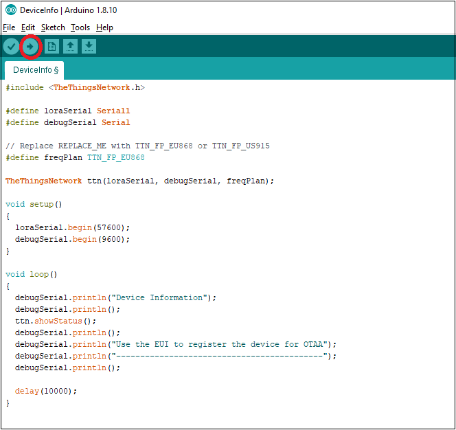
Load the following sketch:File -> Examples -> TheThingsNetwork -> DeviceInfo
In the DeviceInfo sketch locate the line
#define freqPlan REPLACE_ME
and replace the phrase REPLACE_ME with TTN_FP_EU868
Upload the sketch using the Upload button (as shown below)
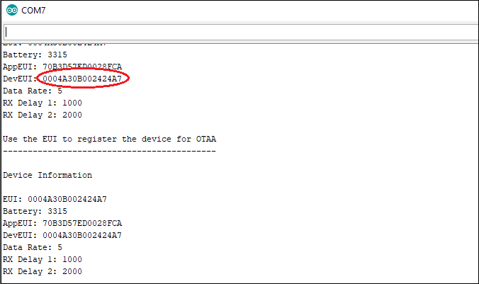
Open the Serial Monitor:Tools -> Serial Monitor
and copy the DevEUI value as shown below:
Open a browser and navigate to the the Application for this workshop on the Things Network

In the Devices section click on ‘register device'. In the ‘Device ID' box enter a suitable name of your choosing for the device.
In the ‘Device EUI' box paste the value of the DevEUI from the previous section.
Finally, click on the Register button at the bottom right of your screen. Your device is now registered with the application.
Return to the Arduino IDE and open your sense-and-sensing-lab-1 sketch
At the very top of the sketch add the following line
#include <TheThingsNetwork.h>
Find the line #include <DHT.h> and below it add add code:
// Set your AppEUI and AppKey
const char *appEui = "<APP_EUI>";
const char *appKey = "<APP_KEY>";
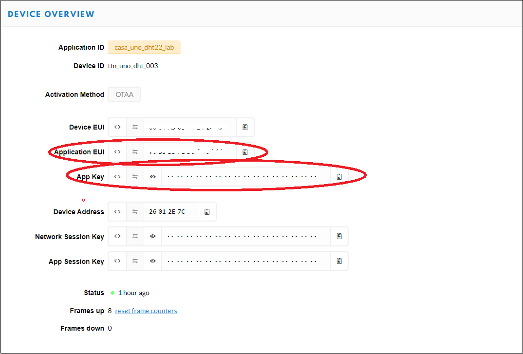
You will need to replace <APP_EUI> with the actual value of your Application_EUI copied from the Things Network console Device Overview (see below). Similarly, replace <APP_KEY> with the actual value of your App Key obtained from the Things Network console Device Overview. (Hint: scroll to bottom of Device Information page if you prefer to copy paste...)
Now find the line #define debugSerial Serial1 and below it add the following to create a serial connection to the Lora communication interface (Note, the ‘other' Serial connection is to your terminal so that you can see debug data):
#define loraSerial Serial1
Immediately below this add the following code to set our region to be EU:
#define freqPlan TTN_FP_EU868
Below the line DHT dht(DHTPIN, DHTTYPE); add the following code to create a constructor to setup a TTN object:
TheThingsNetwork ttn(loraSerial, debugSerial, freqPlan);
In the setup() code find the line debugSerial.begin(9600); and add the following line below it to open the connection to the Lora radio:
loraSerial.begin(57600);
Find the line dht.begin(); and add the following code below it to establish a connection to the Lora Gateway:
  ttn.showStatus();
  debugSerial.println("-- JOIN");
  ttn.join(appEui, appKey);
To minimise the size of the payload transmitted over LoRa, it is necessary to convert our sensor values to unsigned integers. To avoid loosing precision we multiply the sensor values by 100 (applying the reverse transformation at the Things Network backend).
In the loop() code find the line debugSerial.println(Lux); and add the following below it:
uint16_t light = 100*Lux;
Find the following line float humidity = dht.readHumidity(false); and change it to:
uint16_t humidity = 100*dht.readHumidity(false);
Similarly find the line float temperature = dht.readTemperature(false); and change it to:
uint16_t temperature = 100*dht.readTemperature(false);
Now will convert our sensor values to binary and upload them to the ThingsNetwork. Below the line uint16_t temperature = 100*dht.readTemperature(false); add the follwing:
  // Split both words (16 bits) into 2 bytes of 8
  byte payload[6];
  payload[0] = highByte(temperature);
  payload[1] = lowByte(temperature);
  payload[2] = highByte(humidity);
  payload[3] = lowByte(humidity);
  payload[4] = highByte(light);
  payload[5] = lowByte(light);
Below the line debugSerial.println(humidity); add some debug code to print out the light variable:
  debugSerial.print("Light: ");
  debugSerial.println(light);
And below this add a line to upload the data to the Things Network as shown below
ttn.sendBytes(payload, sizeof(payload));
Your sketch should now look like this:
#include <TheThingsNetwork.h>
// First install "DHT sensor library" via the Library Manager
#include <DHT.h>

// Set your AppEUI and AppKey
const char *appEui = "Your App EUI";
const char *appKey = "Your App Key";

#define debugSerial Serial
#define loraSerial Serial1

// Replace REPLACE_ME with TTN_FP_EU868 or TTN_FP_US915
#define freqPlan TTN_FP_EU868

#define DHTPIN 2  //Digital Pin 2
#define DHTTYPE DHT22
#define lightPin A0

DHT dht(DHTPIN, DHTTYPE);

//Calls the constructor for the TheThingsNetwork class from the TheThingsNetwork library
TheThingsNetwork ttn(loraSerial, debugSerial, freqPlan);

void setup(){

  debugSerial.begin(9600);
  loraSerial.begin(57600);

  // Wait a maximum of 10s for Serial Monitor
  while (!debugSerial && millis() < 10000)
    ;

  //Initialise the DHT sensor
  dht.begin();

  ttn.showStatus();
  debugSerial.println("-- JOIN");
  ttn.join(appEui, appKey);

}


void loop(){
  debugSerial.println("-- LOOP");

  float ldr = 5.0*analogRead(lightPin)/1024;
  debugSerial.print("ldr voltage: ");
  debugSerial.println(ldr);

  float Rldr = (50.0/ldr) - 10;
  debugSerial.print("LDR resistance (kOhms): ");
  debugSerial.println(Rldr);

  float Lux = 111.0 - (100.0*Rldr/9.0);
  debugSerial.print("Light levels in Lux: ");
  debugSerial.println(Lux);
  uint16_t light = 100*Lux;

  uint16_t humidity = 100*dht.readHumidity(false);

  // false: Celsius (default)
  // true: Farenheit
  uint16_t temperature = 100*dht.readTemperature(false);

  // Split both words (16 bits) into 2 bytes of 8
  byte payload[6];
  payload[0] = highByte(temperature);
  payload[1] = lowByte(temperature);
  payload[2] = highByte(humidity);
  payload[3] = lowByte(humidity);
  payload[4] = highByte(light);
  payload[5] = lowByte(light);


  debugSerial.print("Temperature: ");
  debugSerial.println(temperature);
  debugSerial.print("Humidity: ");
  debugSerial.println(humidity);
  debugSerial.print("Light: ");
  debugSerial.println(light);

  ttn.sendBytes(payload, sizeof(payload));

  delay(20000);
}
Compile the code and once you have the code compiling sucessfully you can upload the sketch to the Things Uno board.
Save the sketch.
Now return to the Things Network console for your device and open the Data tab (see below):
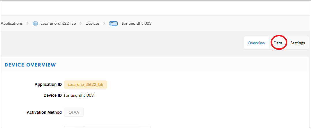
You should be able to see the data uploaded by your device.
To dig a little deeper into how messages can be sent to and from the Things Uno take a look at the quick start guide on TTN
Currently, we have used a simple linear model for calibrating the LDR. However, a linear relationship is not the best model for the relationship between the resistance of an LDR and light levels. How could it be improved? We will look at this further next week.