To complete this workshop, you will need:
- Fusion 360, part of the Autodesk Suite
- A Mouse connected to your computer
You should have previously worked through the CASA0016 Week 7 workshop on PCB design available here.
You task is to design a plant monitor PCB similar to the one used in CASA0-0014. Here is the circuit diagram for this simplified plant monitor.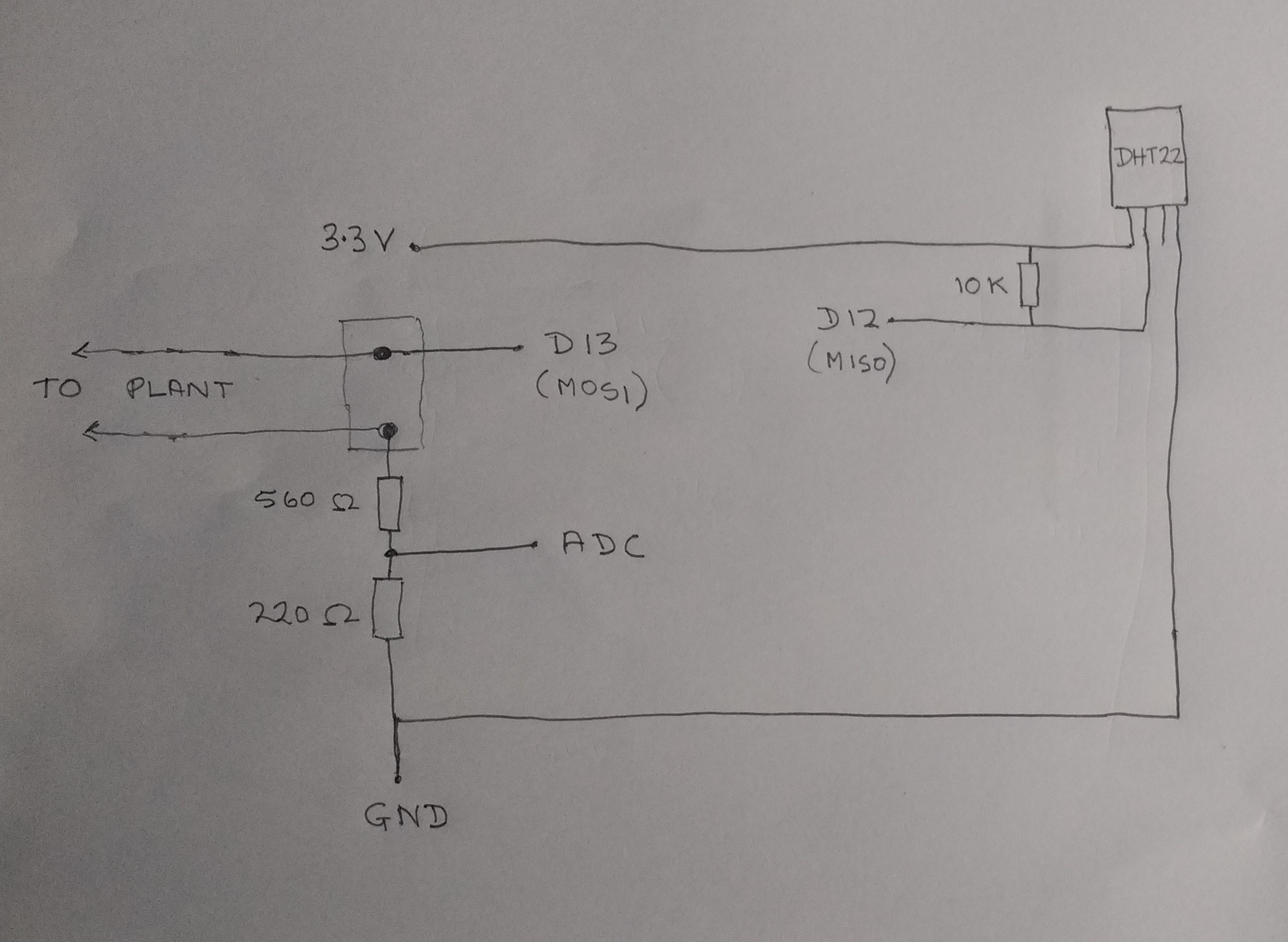
In previous years we used Eagle CAD (which was part of the Autodesk suite) for this workshop. However, recently Eagle CAD was integrated into Fusion 360 so now we will be using Fusion 360 for PCB design. I have created a skeleton Fusion 360 project to get you started containing a schematic containing the relevant parts you will need and a PCB board design sized for Feather Huzzah, with the header holes correctly postioned.
Download the Fusion 360 skeleton project from Moodle onto your laptop.
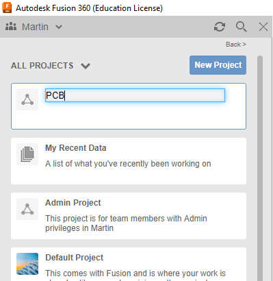
Now start Fusion 360. Create a new project folder (see below)
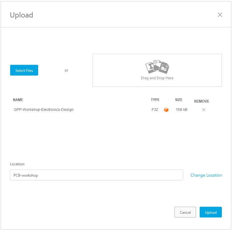
and upload the project file into it (see below).
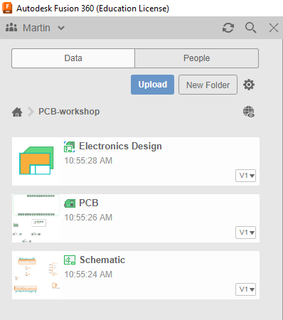
Your project folder should now look something like this (see below)
Double click on the ‘Electronics Design' file. This should open both the Schematic and PCB views.
You will also need the parts library for this project. Download the parts library from Moodle to your laptop.
Now upload the parts library into your Fusion 360 project.
Open the Library Manager (refer to the ‘Prerequisites' section if you don't know how to do this).
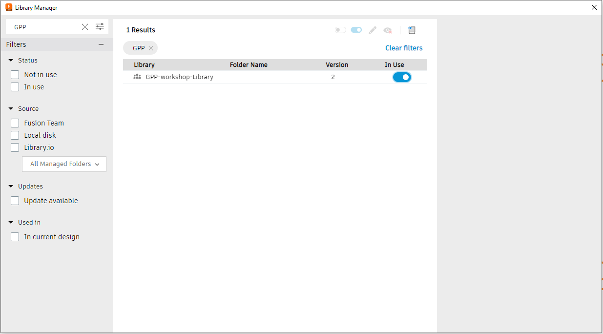
Use the ‘Filter results' field to find the libary you just uploaded (filter on ‘GPP') and set to ‘In Use' (see below)
- Select the ‘Schematic' in your project data (see below)
- First connect up the schematic to reflect the arrangement shown in the circuit diagram above (refer to the ‘Prerequisites' section if you don't know how to do this).
- Once you have done this, run an Electrical Rule Check (ERC) to check there are no errors (refer to the ‘Prerequisites' section if you don't know how to do this). If there are errors you will need to fix them .
- Select the ‘PCB' in your project data (see below).
- Position the parts appropriately on the board (refer to the ‘Prerequisites' section if you don't know how to do this). You should not change the dimensions of the board.
- When you have positioned the parts to your satisfaction run the autorouter tool to route the PCB tracks (refer to the ‘Prerequisites' section if you don't know how to do this).
- Finally, generate the Gerber files suitable for PCB fabrication. You need to run the CAM Processor on the board layout (Manufacturing -> CAM Processor) choosing a suitable template such as from System Examples -> Third Party -> OSH Park or Seeed Fusion, selecting the _2_layer.cam option. You should be able to view the generated Gerber files in a suitable Gerber viewer (e.g. https://www.pcbway.com/project/OnlineGerberViewer.html)
As an optional exercise, if you have time to spare you could try creating a silk screen for your board (refer to the ‘Prerequisites' section if you don't know how to do this).