This workshop will show you how to:
- Design and Build Objects in Autodesk Fusion 360
- Import Objects into Fusion
- Animate Objects
- Create Technical Drawings
- Export - Ready for Blender/Sketchfab/Unity

To complete this workshop you will need (Note - links need completing)
- An Autodesk Education Account
- Fusion 360
- Illustrator
- Node MCU
- SG90 Servo
- LED Backlights (Optional)
- Perspex
- 3D Printer
- Arduino Sketch from Github
Texture and Resources
Textures
[Wind Speed MPH / Beaufort Scale Texture] [Pi Hut Tech Drawing]
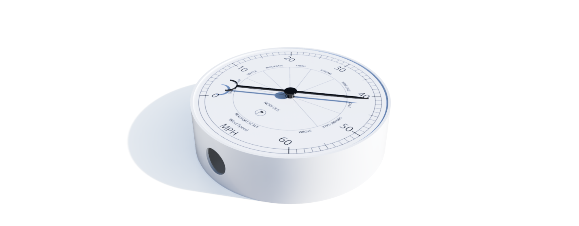
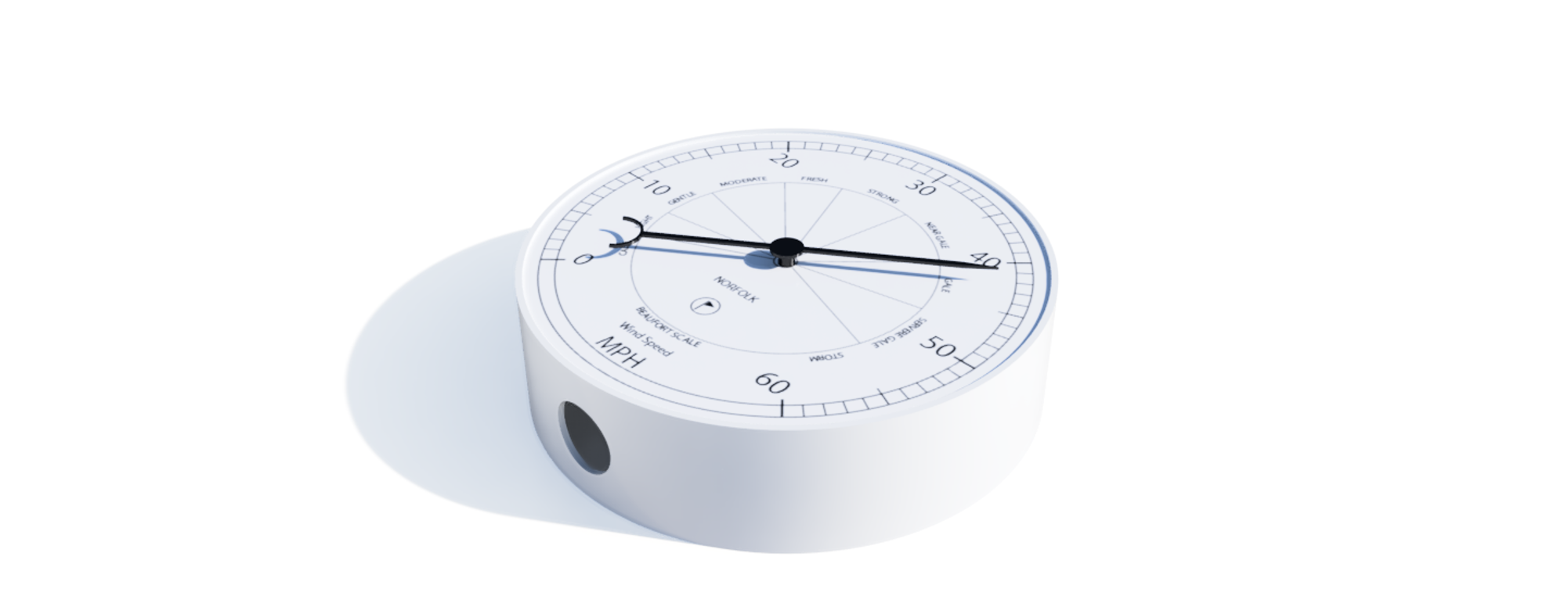
The digital object is the basis for everything - the Physical Object becomes the ‘Twin', rather than the common concept of a ‘Digital Twin'. We will use Fusion 360 to design a Gauge/Dial to display realtime data. This can be from any feed and from any location. It is made to hang on a wall, taking a nod from traditional designs (we discuss more in the Enclosure Lecture) or sit on a desk in physical form.
In digital form it forms the basis for displaying data in both Augmented Reality and Virtual Worlds - completing the circle between the digital and physical device, both linked to realtime data.
Key Requirements
- Ability to display near realtime data (an update every 3 seconds)
- Adaptable to Multiple Data Feeds
- Have a range of 360 degrees
Multiple Parts
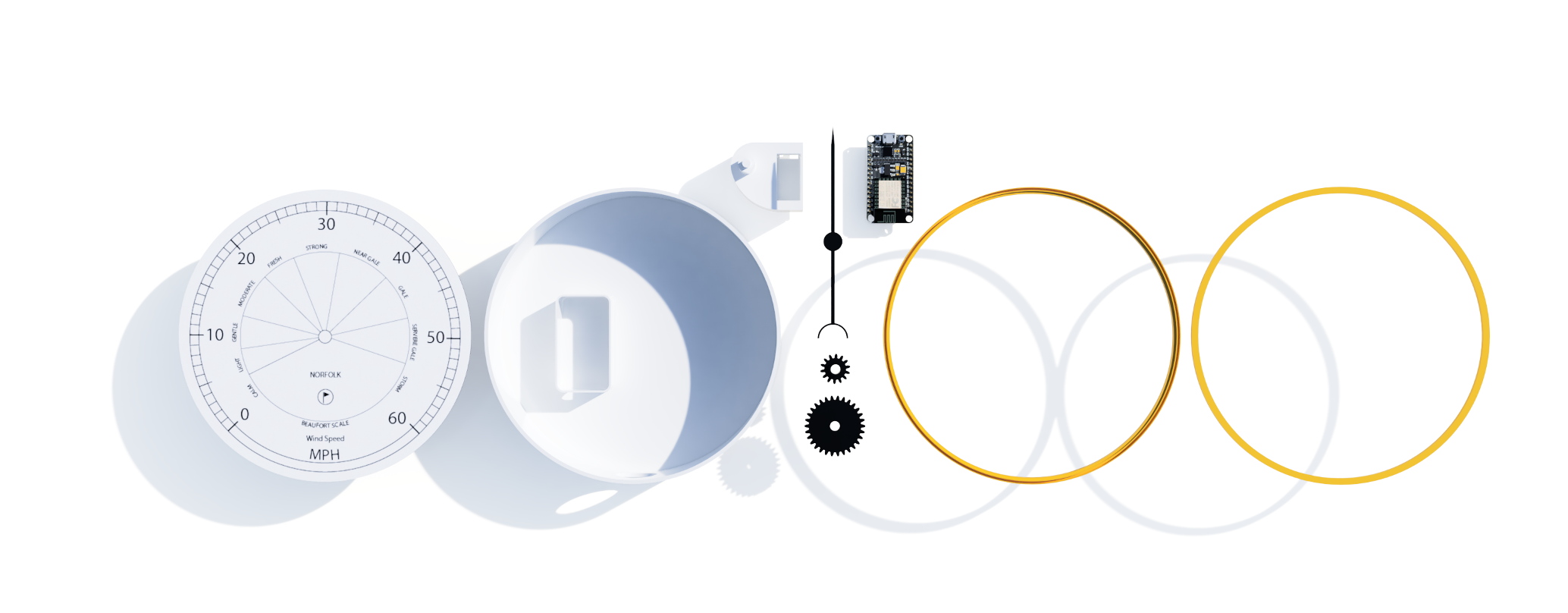
- Gear Train to adapt a 180 degree servo to 360
- Base and holder for the main components
- Node MCU Holder
- LED BackLights
- Dial (via Adobe Illustrator)
- Dial Holder
- Needle/Pointer
- Perspex Holder
The Servo Holder and Gear Train are arguably the main part of the data gauge. Our Servo - the SG90 - was selected due to both its low cost and ability to know its last position, making it relatively easy to map data feeds to movement.

Other options include a Stepper Motor - these negate the need for a Gear Train but require ‘zeroing' on every start up and can run hot when used for long periods of time.
In these first steps we will explore the following concepts in Fusion 360:
- Components
- Sketches
- Offset
- Fillet
- Projection on Face
- Press/Pull
- Cut
- Spur Gears
- Importing Mesh
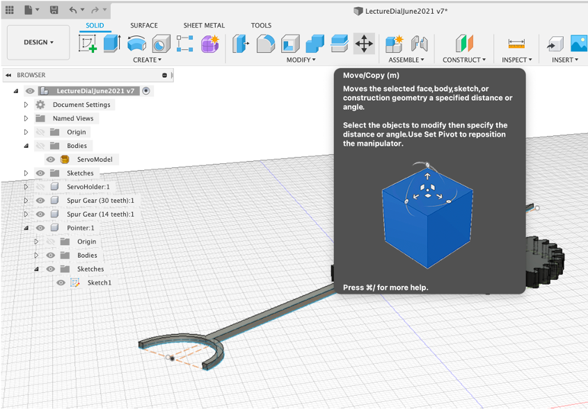
- Move/Rotate
- Capture Position
- Visibility
These are the core skills required and we will reuse them throughout the whole build.
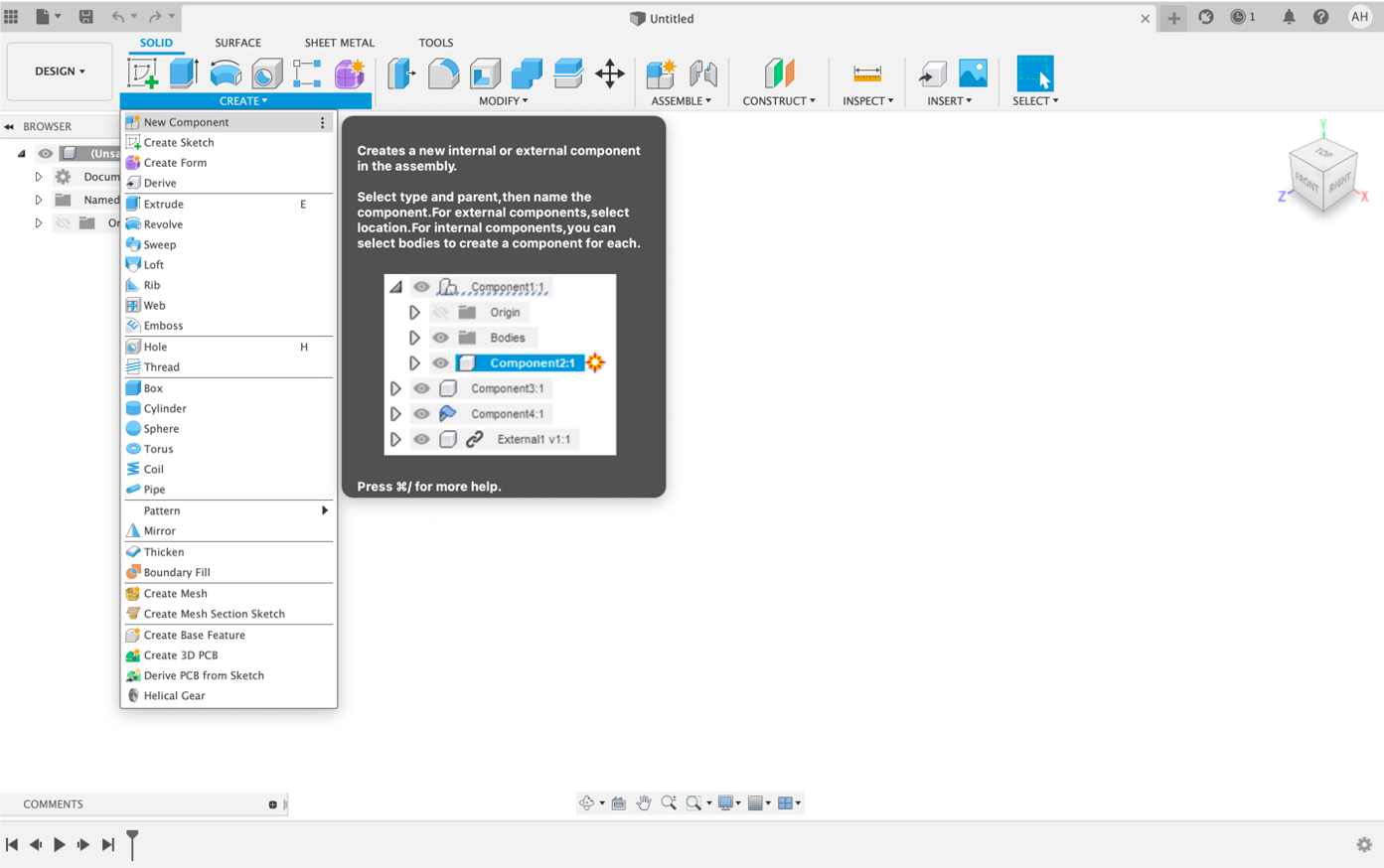
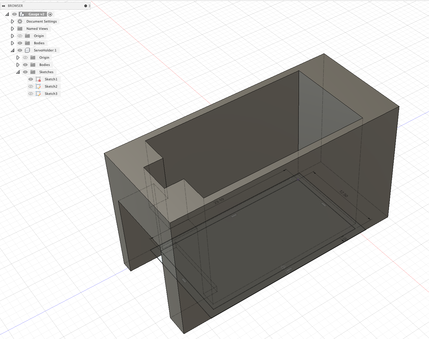
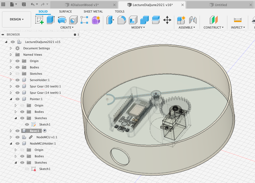
First Steps - A New Component
An object in Fusion360 is made up of multiple components. It provides a structure to the model and allows a complex model to remain navigable.
It is important to always aim for a logical structure in Fusion 360.
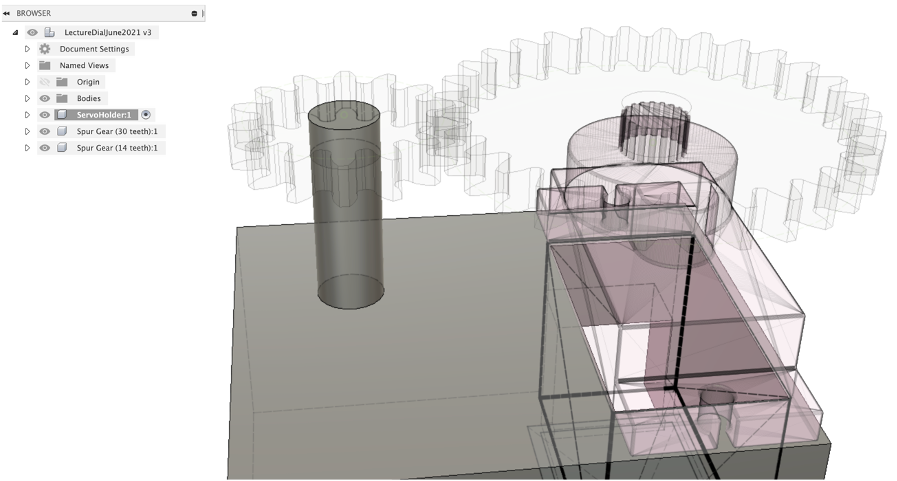
Lets create our first Component - Create New Component
Give your Component a name ServoHolder and Save your file.
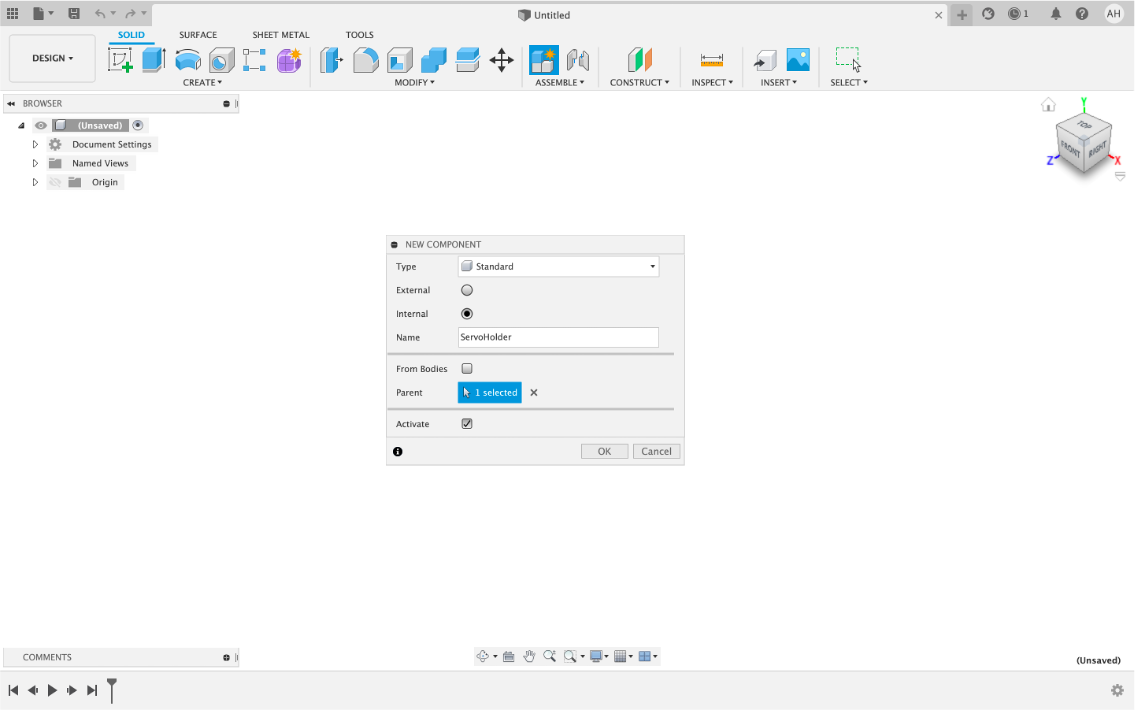
You now have an empty Component ready to be filled with a 3D model.
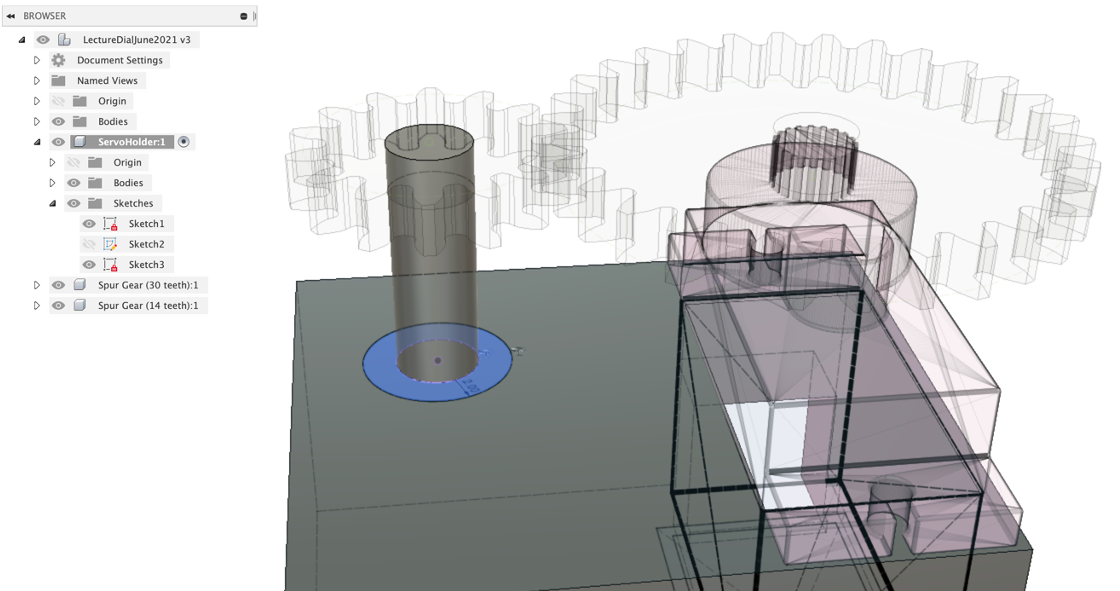
First Steps - Create a Sketch
Sketches form the basis of Components. You can select a plane of a face on which to draw a sketch , they contain the dimensions and the 2D layout of your Components. You can go back at any point and edit a Sketch to, for example, change a Dimension and the relative Component will automatically update itself.
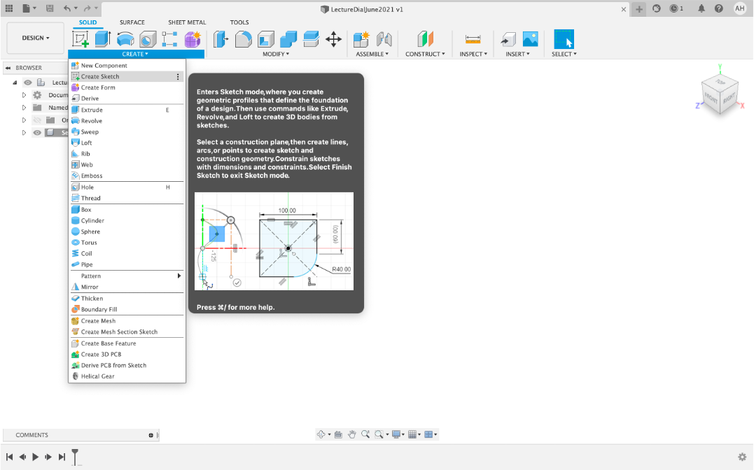
Create a New Sketch and click on the flat plane to select the surface location. This creates our first empty sketch.
Before we add anything into our first Sketch we need to know the dimensions of our Servo.
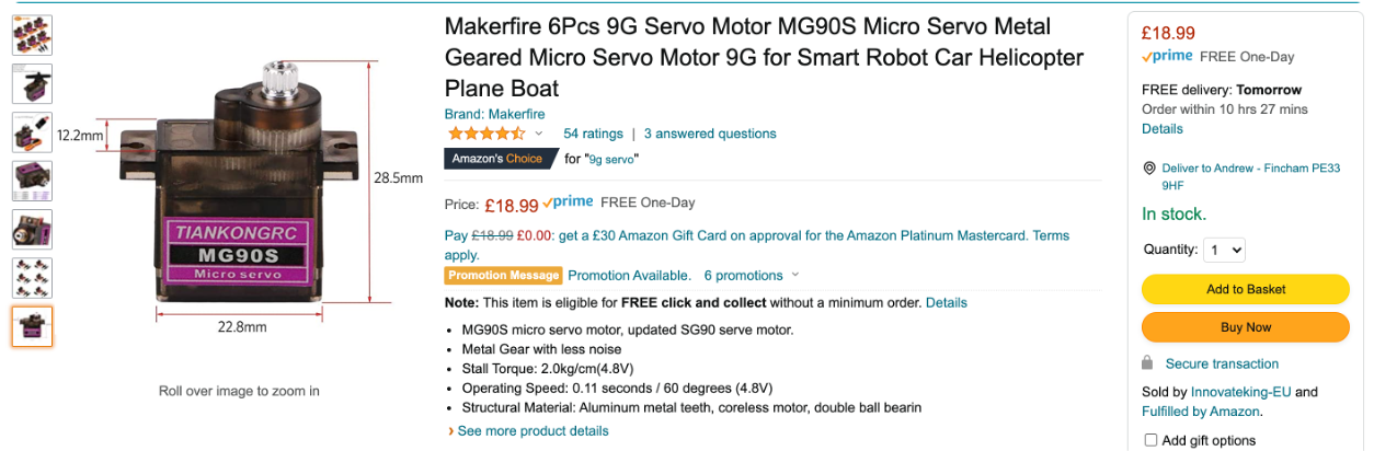
The servo is listed as 22.8 x 12.2 x 18 mm. We are going to make a holder for the servo which simply slots in - this requires a tight fit. A good measure to use for ‘snap in' connectors, lids, components is and additional 0.3mm to the original size. This is dependent on the 3D printer, settings and filaments used so it is open to adjustment. A safer method would be to allow for some play in the holder and to fix it using screws. However, where is the satisfaction in that....
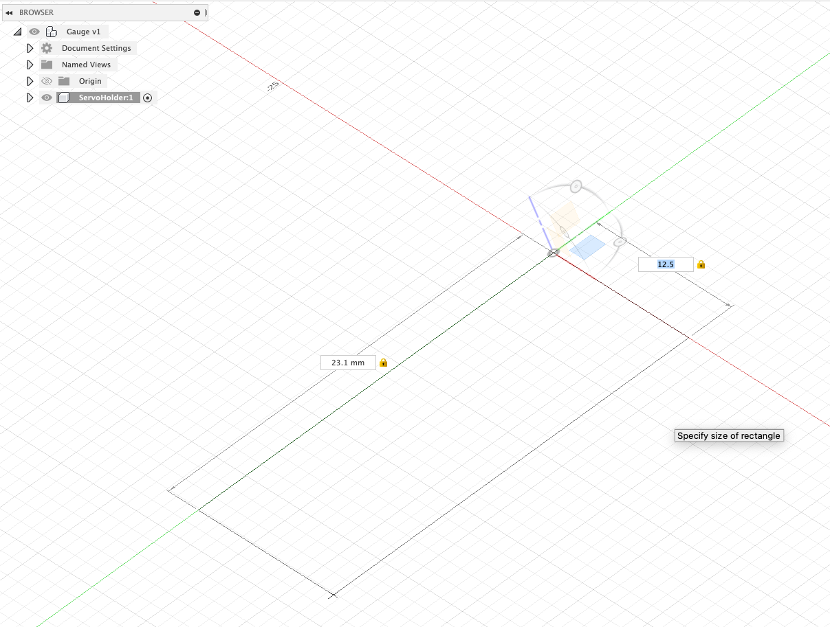
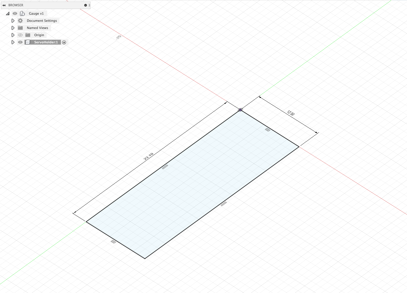
First Steps - A Centre Point Rectangle and Dimensions
‘Create - Rectangle - Centre Point Rectangle'
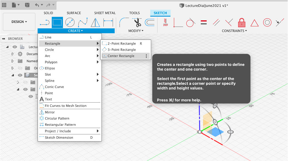
Drag out and enter the dimensions, us tab to move between edges. Press enter to confirm.
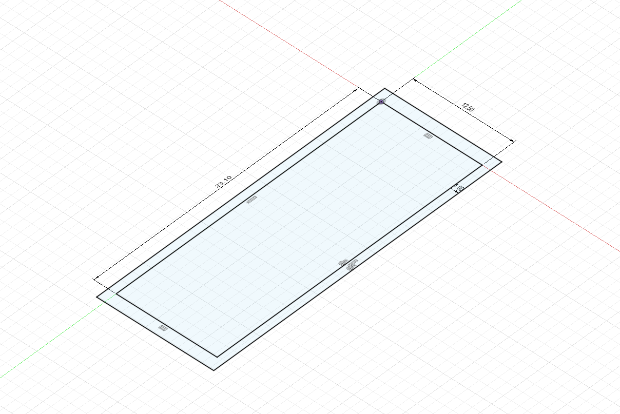
First Steps - Offsets
Offsets are useful to create an offset (obviously!) - ie creating a wall around the initial rectangle. Press o on the keyboard to shortcut and -
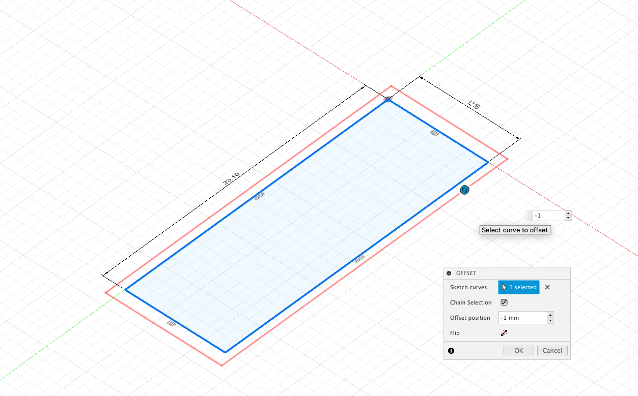
The size of the offset is typed in -1mm (ie outside the box)
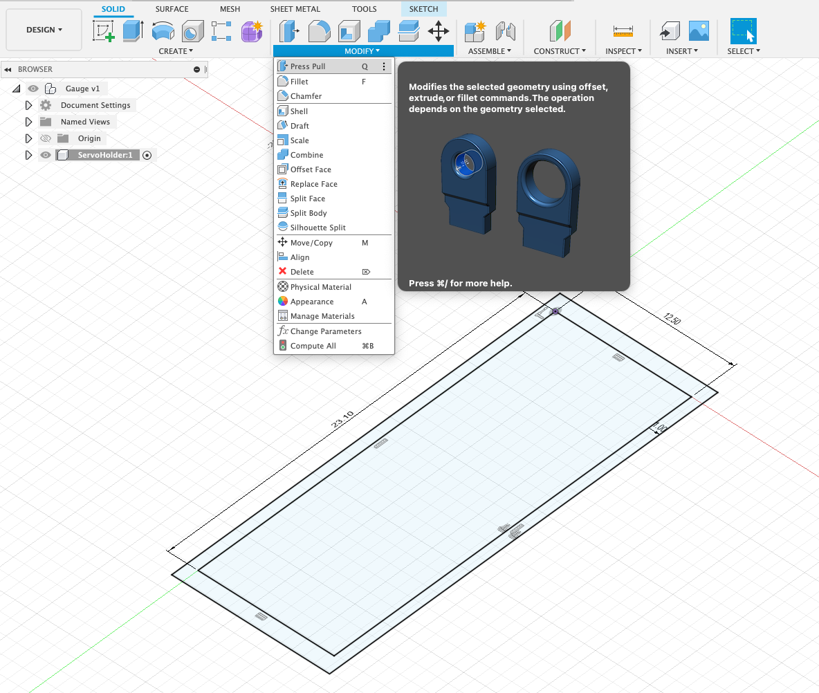
First Steps - Press Pull
‘Press Pull' allows you to move faces up and down - thus the name Press Pull. Highlight the offset, Modify/Press Pull or Q as a useful keyboard shortcut.
The size typed in - 19mm (this is the 18mm height an allowing 1mm for the base of the Gauge)
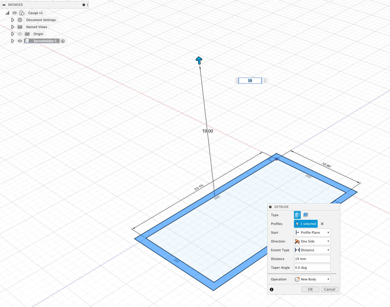
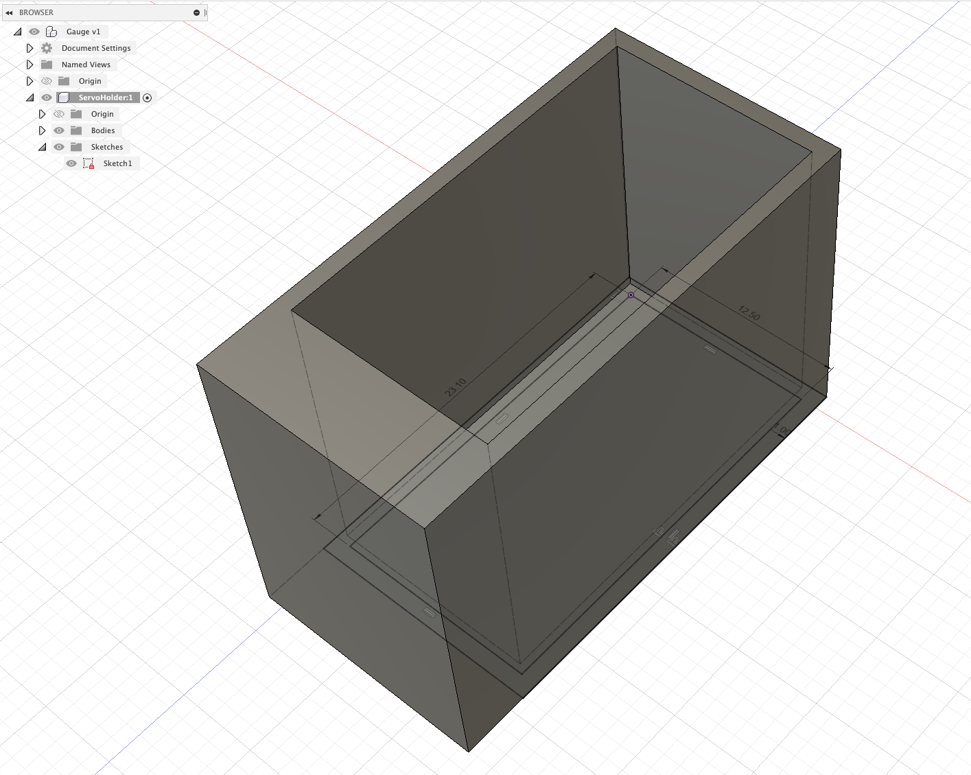
Your component should now look as per:
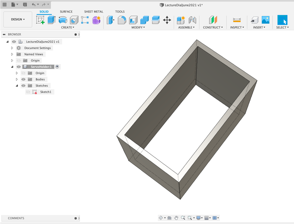
You now need to add the base - note the sketch has disappeared. This is an early quirk to note. Click the eye to reshow the Sketch and Press Pull 1mm.
After all that - you have a box - but the box is the start of the ability to make almost anything in Fusion 360.
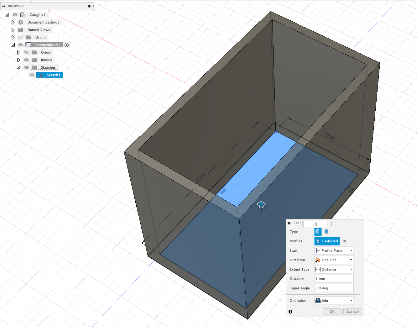
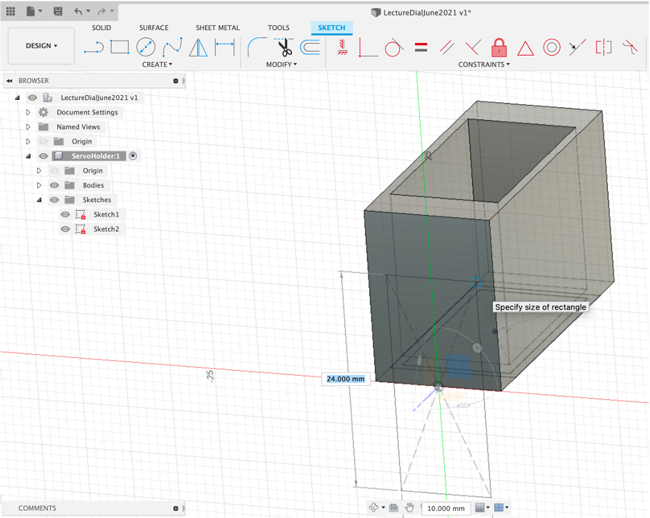
We now want to add the space for the screw tabs - Press Pull on the end face by 4mm.
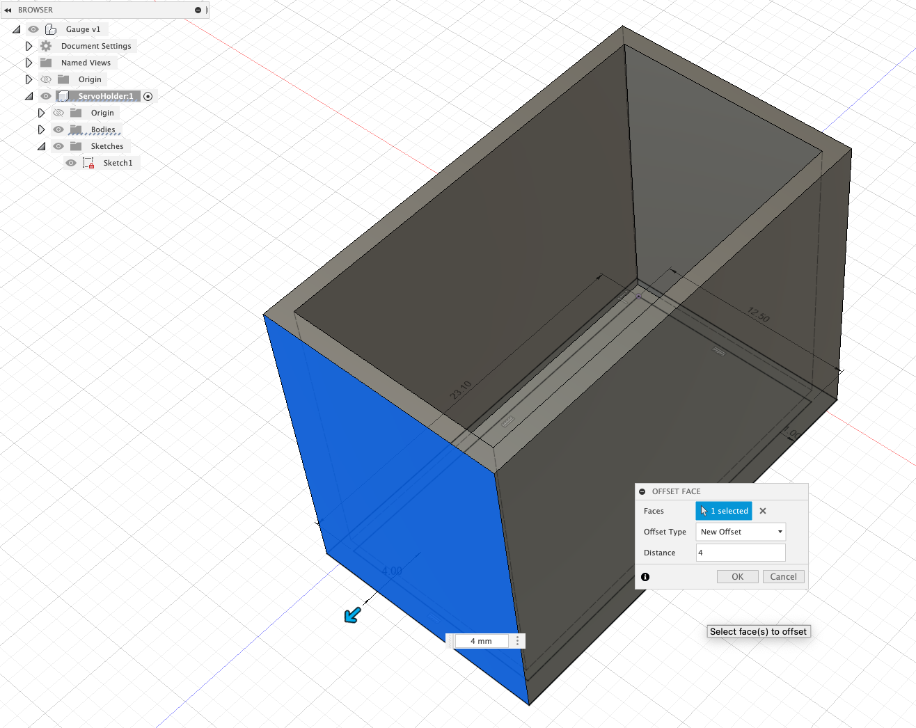
Repeat this for the opposite end - creating a space for the servo to sit.
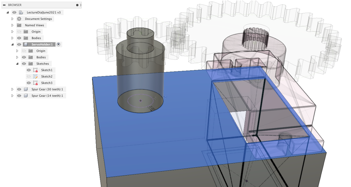
First Steps - Sketch on Faces
Sketches can be made on faces - allowing you to form/cut new shapes.
Select the End Face and Create New Sketch
Add a `Centre Point Rectangle'
Press Pull -7mm and Cut
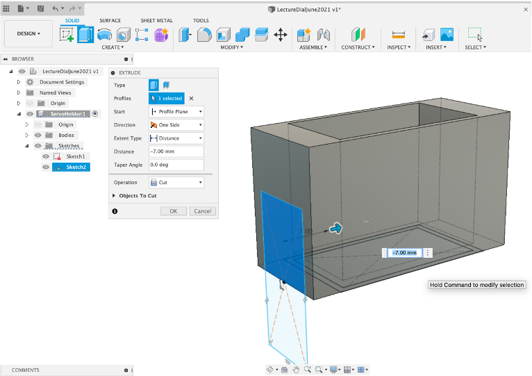
As our size constraints are only 0.3mm the servo will need to be slotted in directly into the slot. Although we have used the Servo dimensions they do not take into account the protruding wire coming out the front. As such we also need to make a slot to allow us to slide in both the servo and the wire.
Select the Top Face and Create New Sketch
Add a `Centre Point Rectangle'
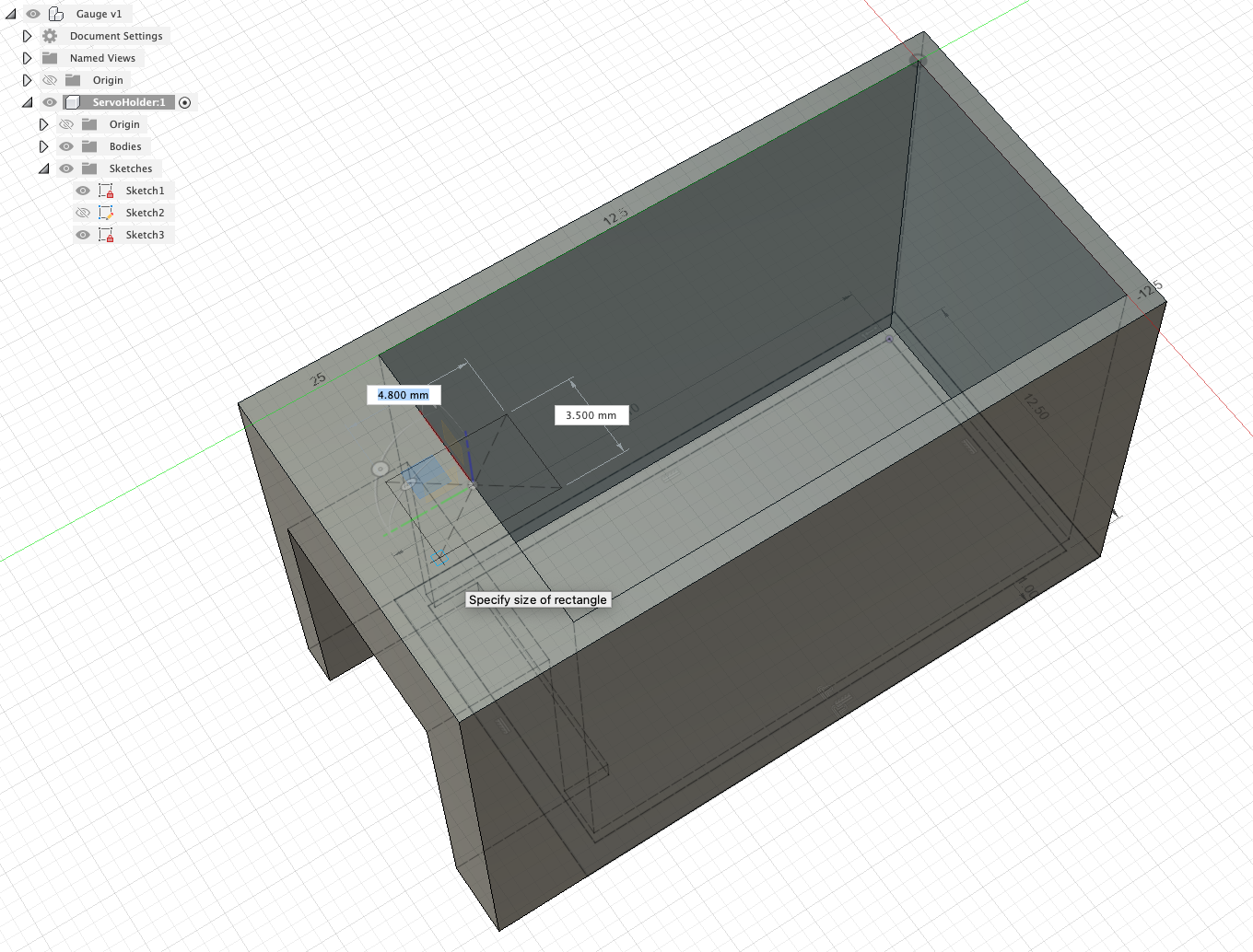
Press Pull until it creates a hole down through the top and Cut
Well done - you have a basic (and a little ugly) Servo Holder.
Importing Objects
As with other 3D modelling platforms Fusion 360 allows the ability to import objects. This can be useful to add new components to you scene and to add reference models.
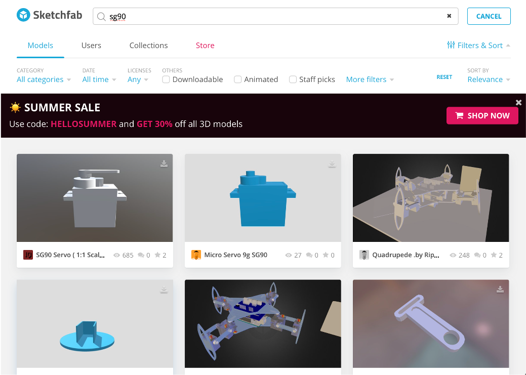
There are two main places to look for models - Sketchfab and the Autodesk Gallery
Insert Mesh
For this walk through we have provided the mesh of a SG90 on our share drive (ADD LINK)
Activate the main scene (to ensure the mesh becomes part of the hierarchy)
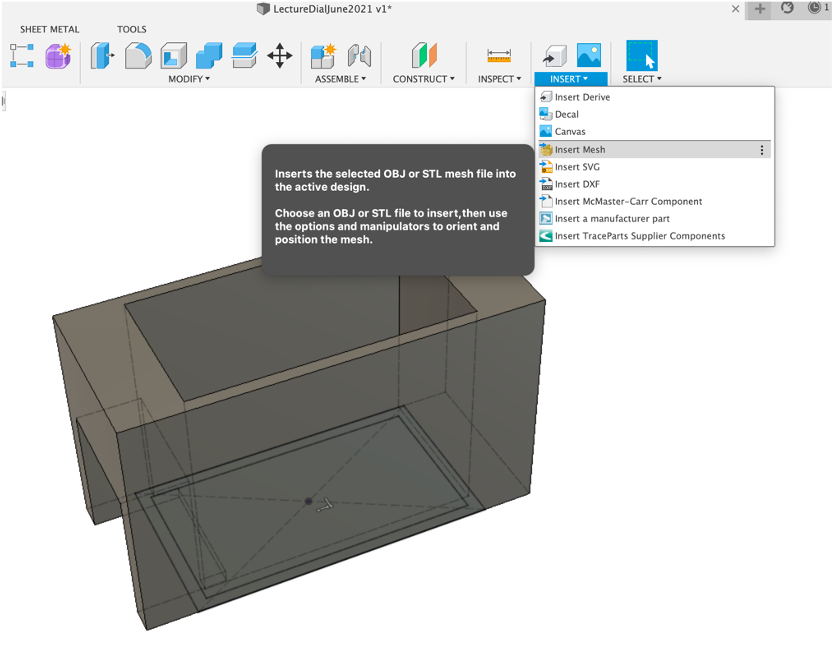
Insert and insert mesh
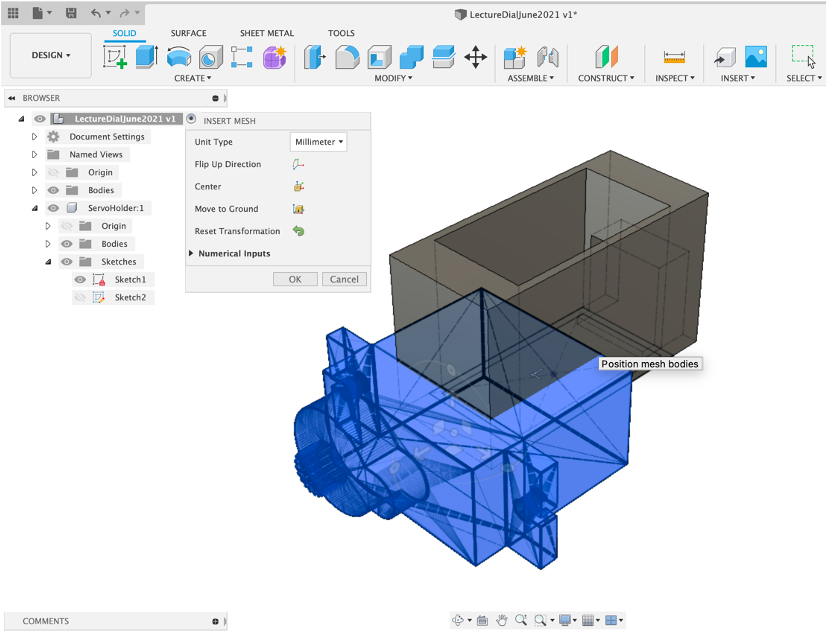
Align the model using the rotate/move arrows using the top/side views. Rename the mesh and note it has been added inside the Bodies tab, as its a mesh.
We use the servo as a reference point for the next part - adding the Gears.
The SG90 Servo rotates by 180 degrees. A gear ratio of 2:1 provides a 360 degree rotation - so a main gear of 30 teeth and secondary gear of 15.
However, as not all servos were made equal it is wise to go over 360 degrees. 2:14 to 1 - 30:14. This allows 385 degrees which allows enough play to calibrate the servo.
Fusion has its own Gear Maker - Tools: Add-ins - Spur Gear and Run. It imports the gear as its own Component.
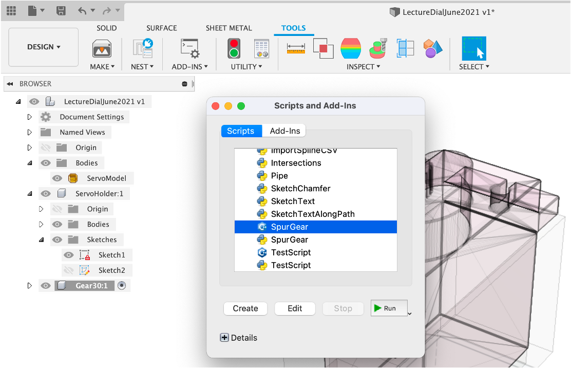
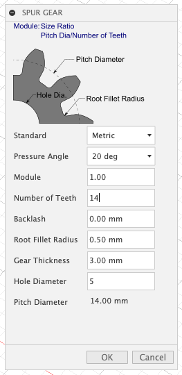
Type in the following settings
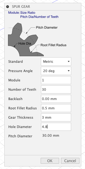
- The Pressure Angle - there are three options - 14.5, 20 and 25. 25 provides more pressure but also noise, 20 is a good mid point to use on most projects.
- Module - Indicates how large/small the gear is - the module needs to be the same setting for all interlinking gears.
- Backlash - The tolerance between the gears. Ours is at 0 - through trial and error - the default is .15 and will also be ok.
- Radius - The size of the tooth
- Gear Thickness - simply the height of the gear
- Hole Diameter - the centre hole size - this is set at 4.8mm to allow a push fitting onto the servo.
Use the Rotate/Move to align and select Capture Position future versions of Fusion will all an align with mesh option but this is currently in beta (July 2021).
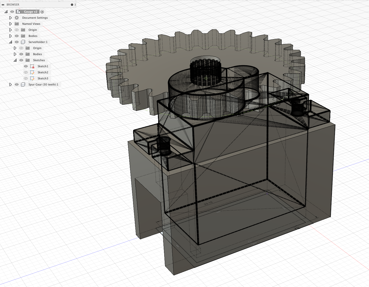
Our alignment is suitable for the level of accuracy required.
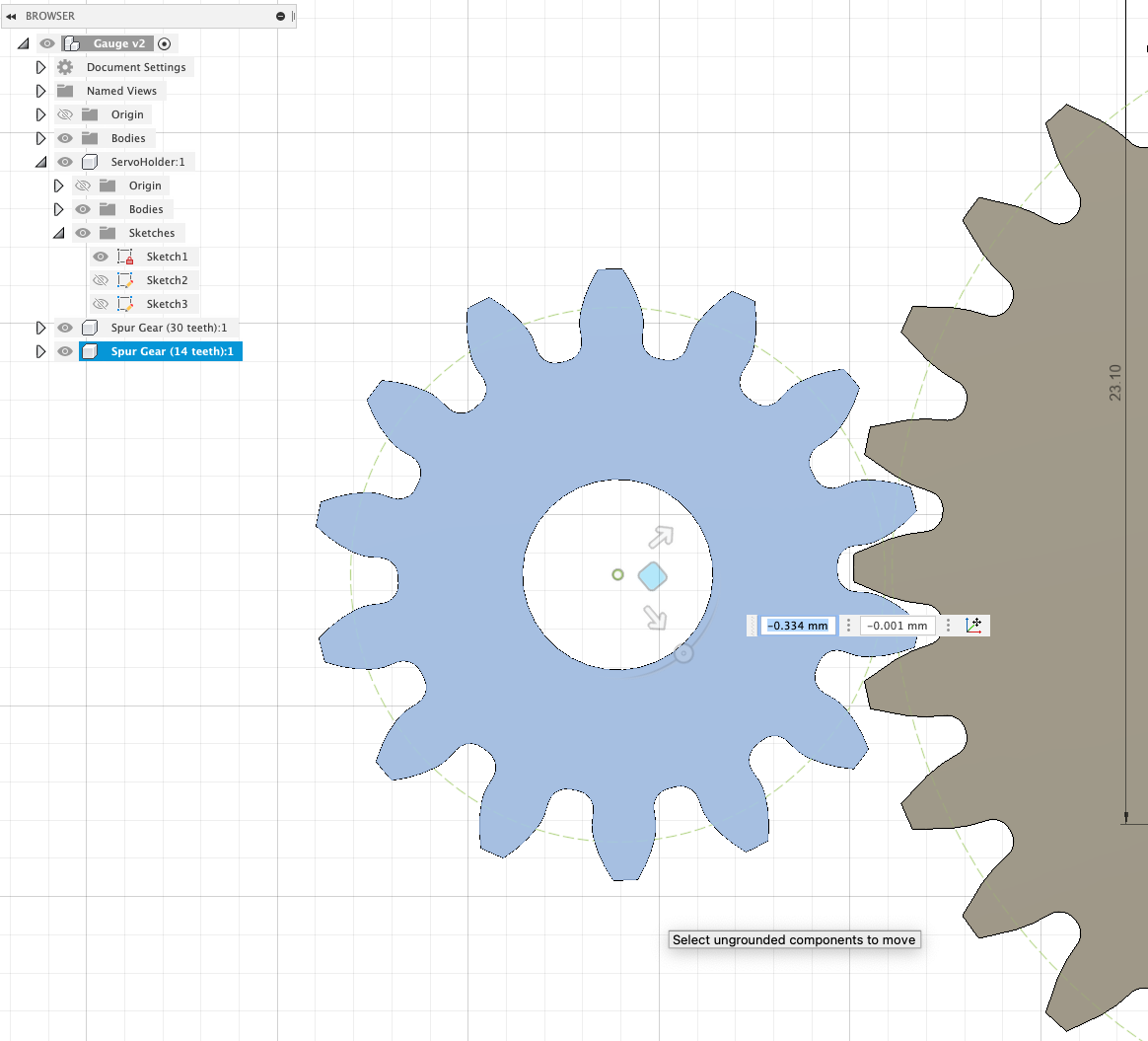
Gauge Gear
As before New Component ,rename Gauge Gear and then Tools: Add-Ins - Spur Gear, Run Settings as below,
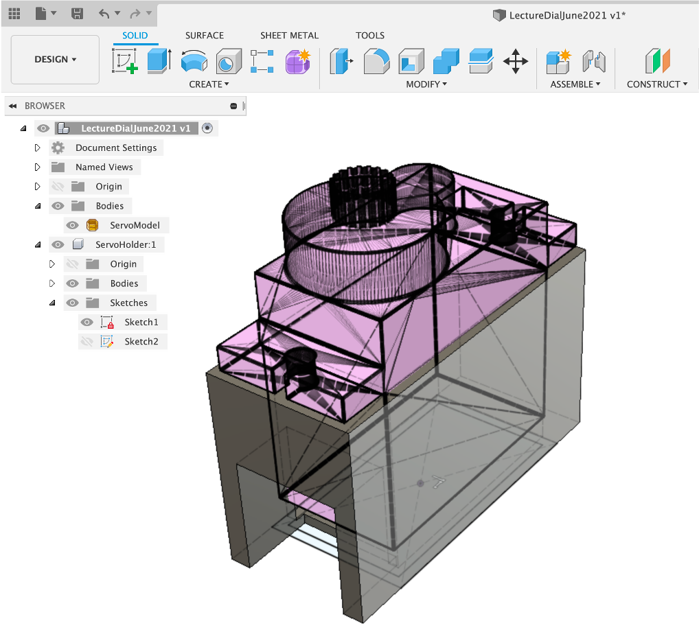
Rotate and move the Gear so the spurs intersect
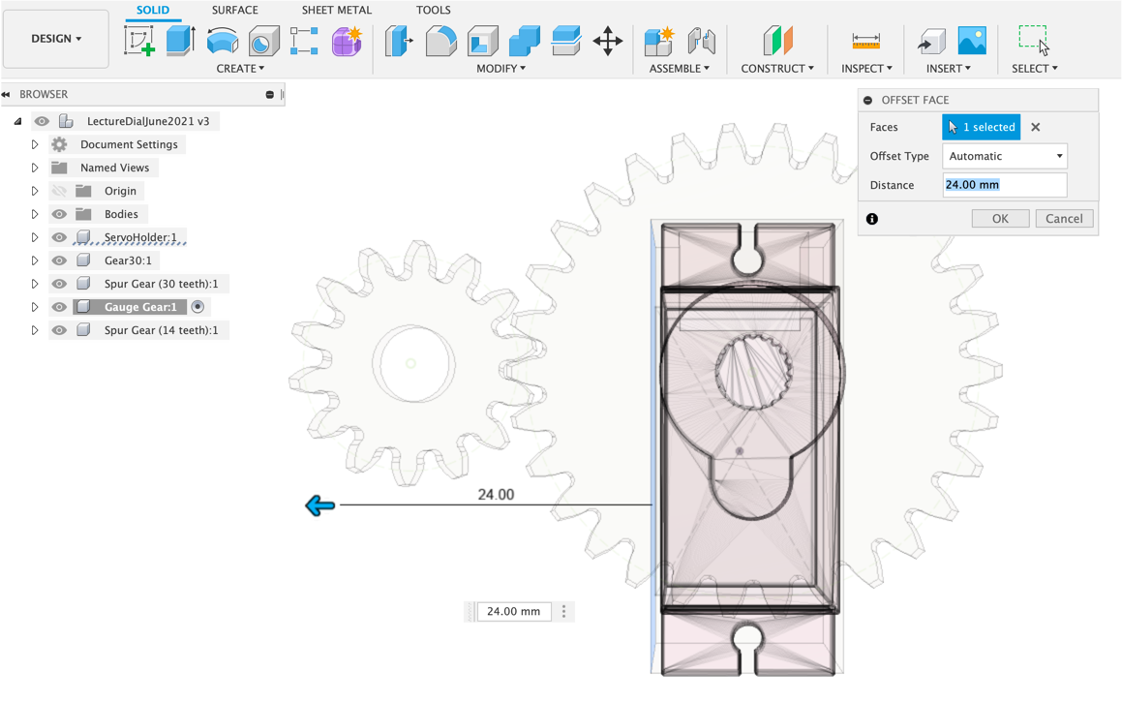
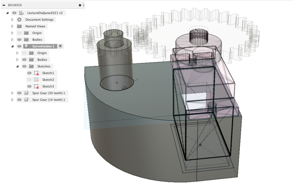
Making the Gear Shaft
We are going to use the edit the servo holder to also include the shaft to hold the second gear.
Press Pull on the side of the servo holder - pull so it extends beyond the gear - 24mm
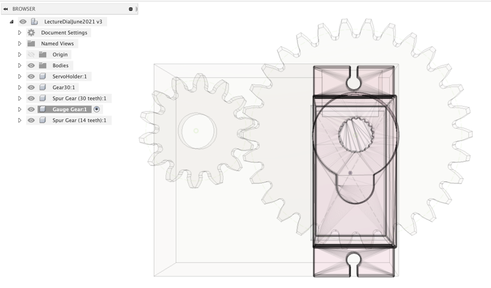
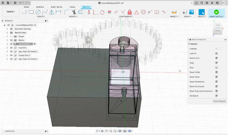
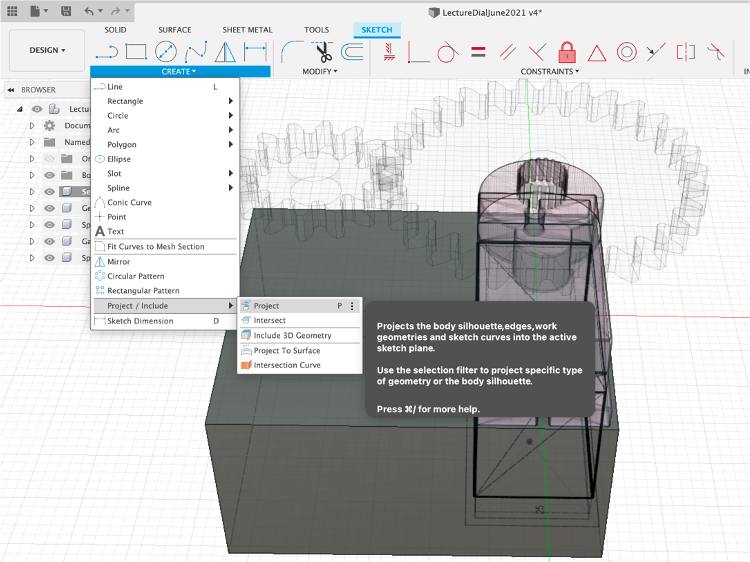
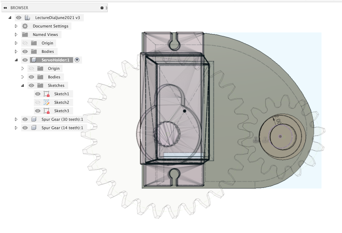
Projection
Projection is an extremely useful feature of Fusion 360. It allows any part of a model to be ‘projected' onto another surface, allowing it be sketched. We are going to project the gear hold onto the surface of the servo holder, to align the shaft.
Active the servo holder and Create New Sketch on the top surface.
Create - Project Select the Centre of the Gauge Gear.
Offset by 2mm, this is go create a shaft on which the Gauge Gear will sit.
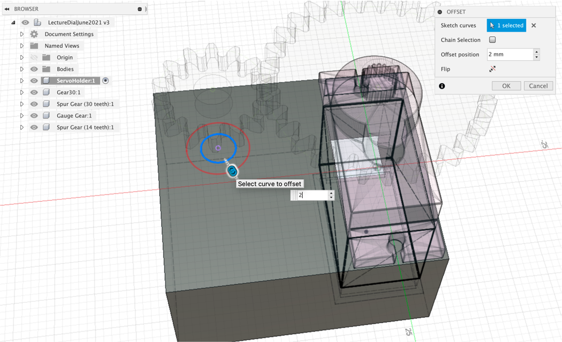
Press Pull to create the Central Shaft and hover the mouse over the Guage Gear - it will snap to the height.
Reactivate your Sketch and `Press Pull the outer offset - this time snap to the bottom of the gear'
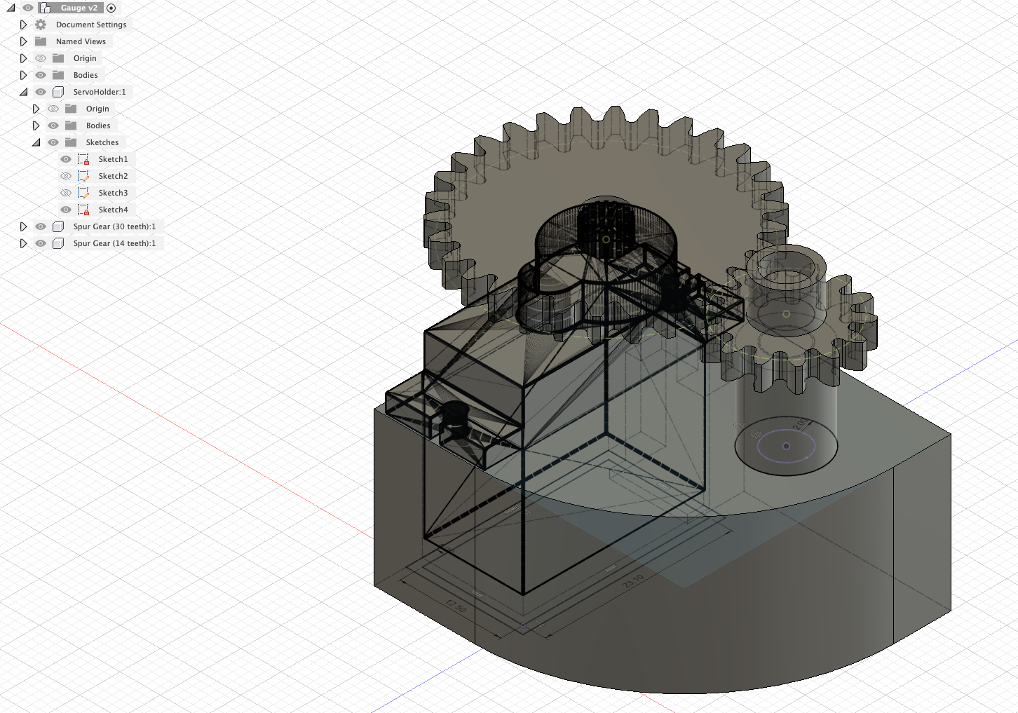
You now have two gears and a servo holder
The final step is to remove some of the unused space and to refine the design.
Filleting adds a curved edge to an object, its a useful way to give a shape some definition after modelling.
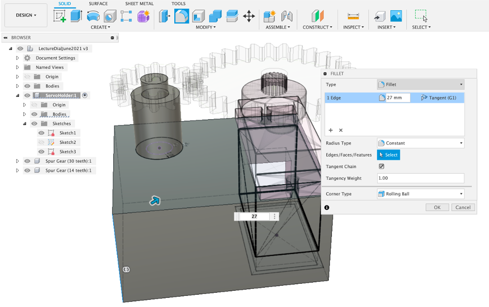
Select the corner edge and tool/fillet (F to shortcut). Fillet according to your own preference.
Select the corner next to the Gear Shaft and again Fillet according to your preference.
The servo holder has now more than a square box - it has some shape and even though it will be hidden away in the physical version, in the augmented reality version it will be viewable for all to see.
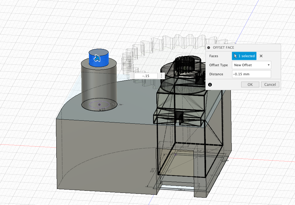
Finally in this section, ee need the Gear to turn freely on the shaft and be close enough that it wont introduce any ‘wobble' to the gear when it is turning. Turn off the Gear Visibility (so you can see the gear shaft). Select the outer surface of the shaft and Press Pull by 0.15mm.
Duration 5 mins
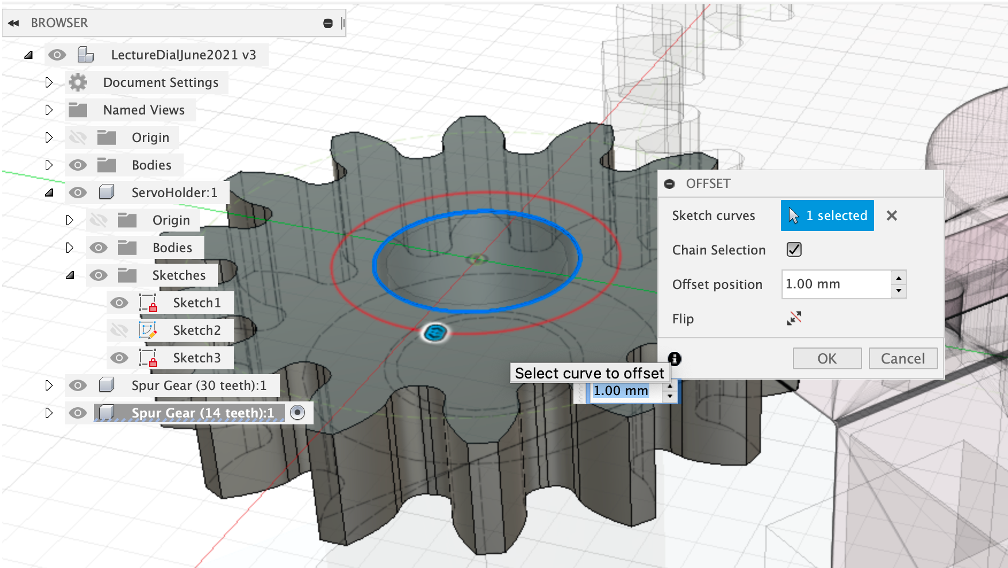
The data pointer (or needle - depending on your choice of term) is central to the overall look of the gauge. It needs fit into the gear so it moves, but not too tightly that it cant be taken out and realigned for calibration.
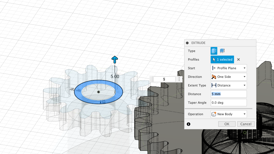
The pointer sits on top of the Gauge Gear - Offset by 1mm to create a ring wall.
Press Pull by 5mm to extrude
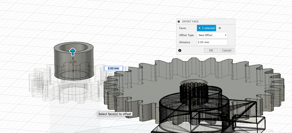
Finally we need to pull up the central shaft - to reduce any movement in the gear. Select the shaft and Press Pull 3mm.
The first iteration of the Servo Holder and Gear Train is complete - well done.
Before we carry on with the modelling - the Pointer/Needle is the next logical step - we are going to pause and explore the 3D Print Process and Rendering in Fusion 360.
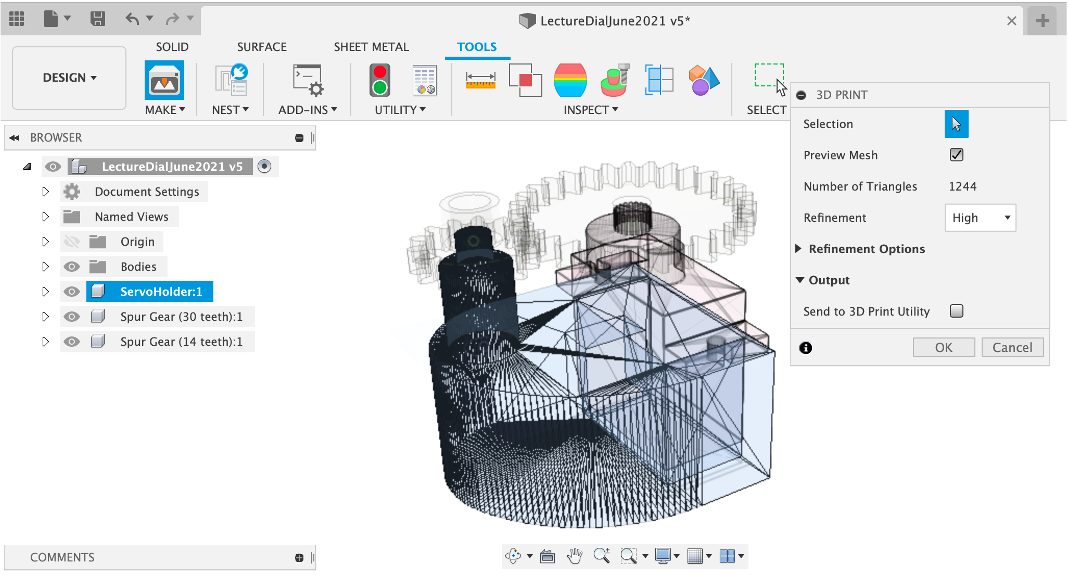
Models from Fusion 360 can be exported for 3D printing (.stl format) via the Make tab.
This section assumes an basic knowledge of 3D printing on the Prusa printers.
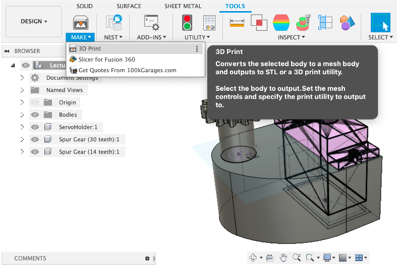
Select the a Component to export and untick the Send to 3D Print Utility option. This allows your to save the file directly to disk and open in your Slicer of choice.
We are using Slicer by Prusa - Load in all the parts after exporting and click the Auto Arrange option. Check all the objects are flat on the print bed and use the 2mm Quality settings. Also check your Octoprint IP Address.
Duration 10
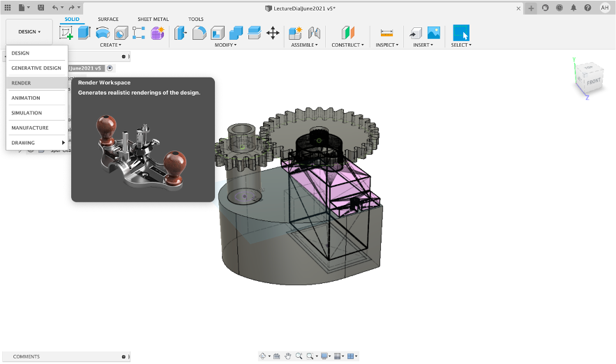
Fusion 360 has a powerful built in render engine. Oddly it only works with single images oe motion studies rather than full animation. It is however worth taking 10 minutes to learn how it works.
Open the Render Work Space
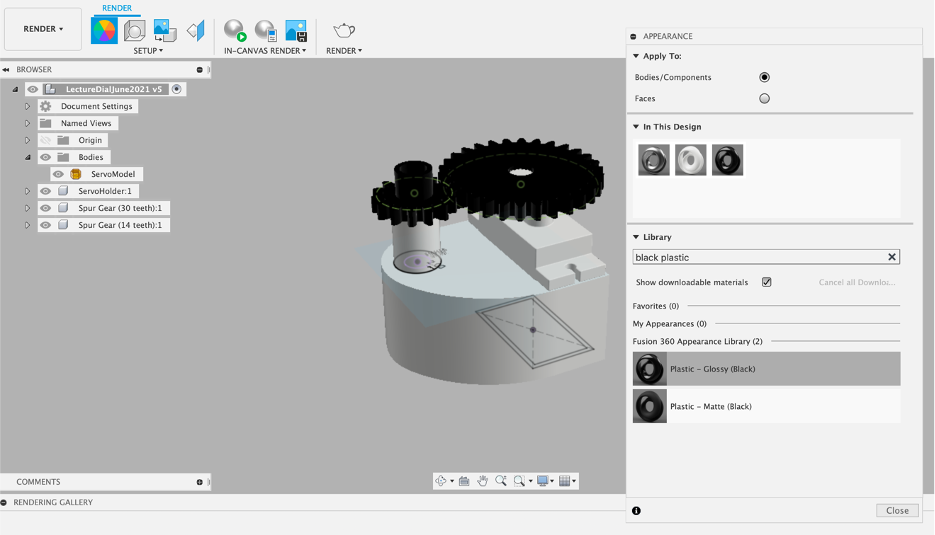
Setup - Appearance this is where we assign materials to our model.
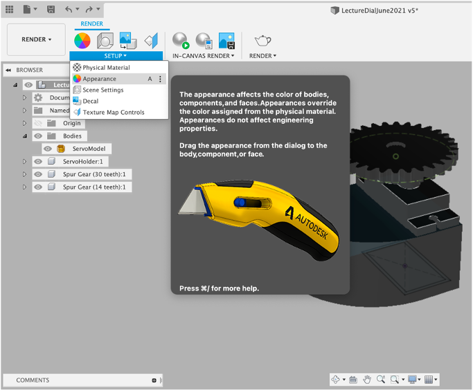
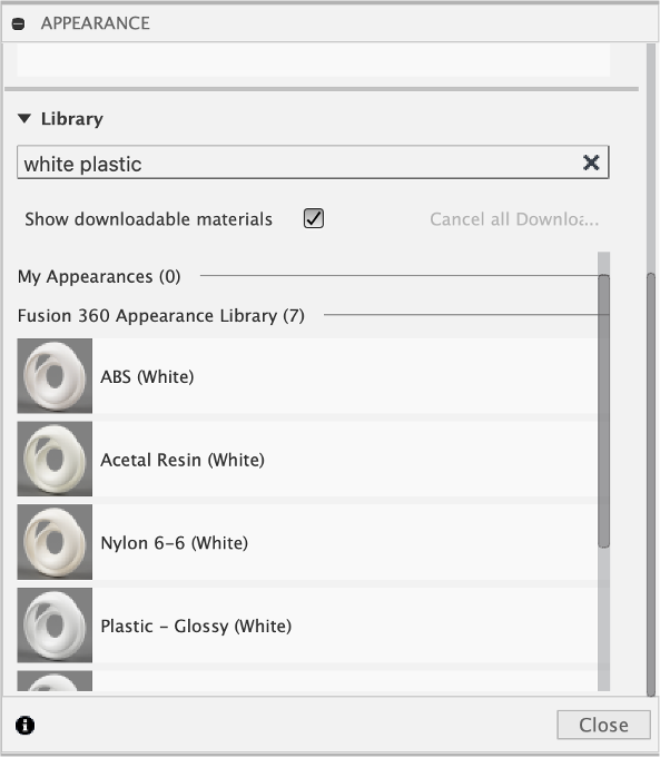
Search for White Plastic.
Click and Drag onto your objects. Add additional materials to your gears, ie Black Plastic.
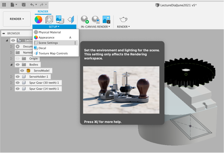
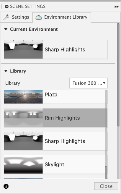
We now need lighting added to our scene. Open the Scene Settings dialog.
Click and Drag onto an option into the scene - light direction/background can be changed in the settings. Lakebed is good for shadows.
Rendering can be carried out either via the Cloud, Locally or..
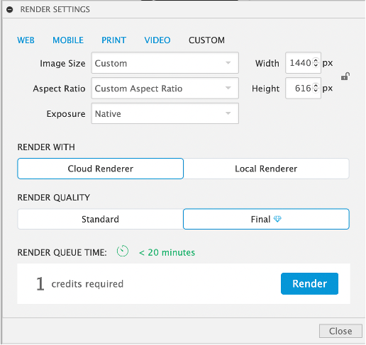
directly in the fusion, workspace. This allows your to quickly check lighting and shadows before running a full render.
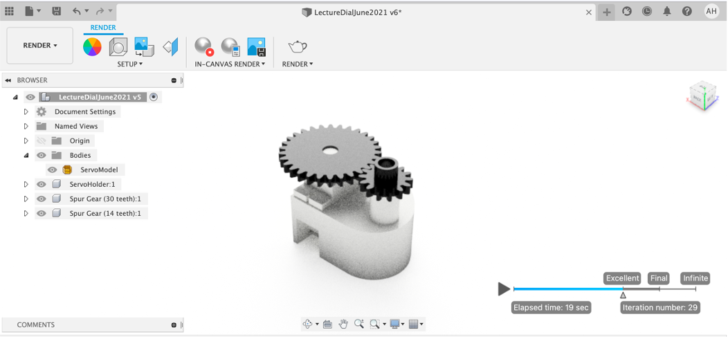
Rendering, either locally or via the cloud provide the following type of output. We use these settings throughout the next steps of 3D modelling.

Concept -
- Adaptable for a variety of gauge sizes.
- Needs to fit into the Main Gauge Gear

Additional Fusion 360 concepts covered in this section:
- Lines
- Arcs
- Trim
- Move

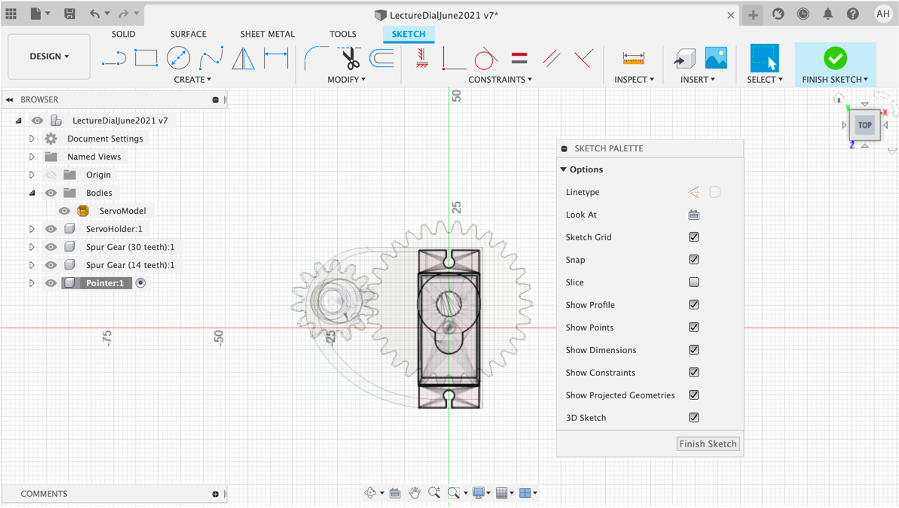
Create a New Component and rename it Pointer (or Needle, Indicator - what ever you choose). Create Sketch.
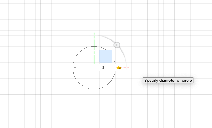
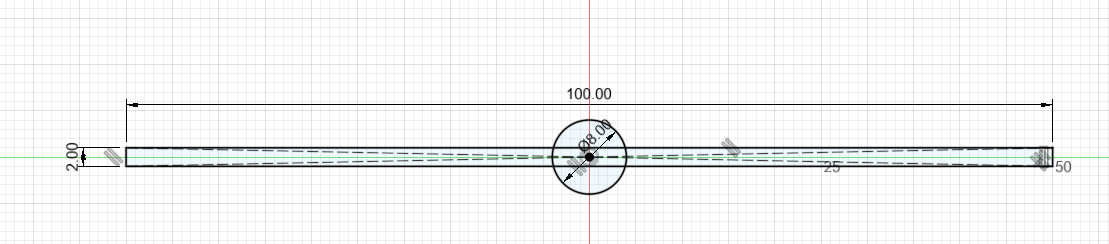
Create - Circle - Centre Diameter Circle
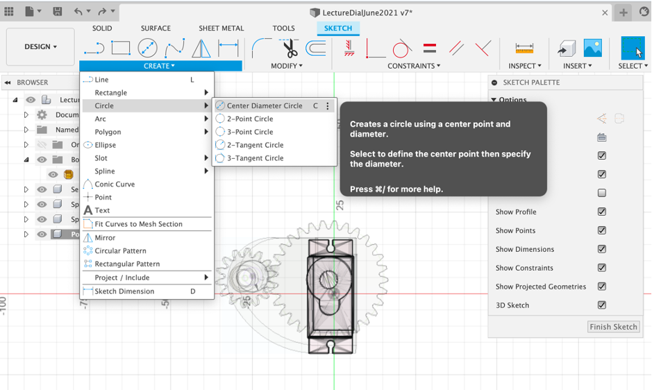
Make it 8mm in size
Now go to Create - Rectangle - Centre Rectangle and drag from the centre of the circle.
Make it 2mm by 100mm
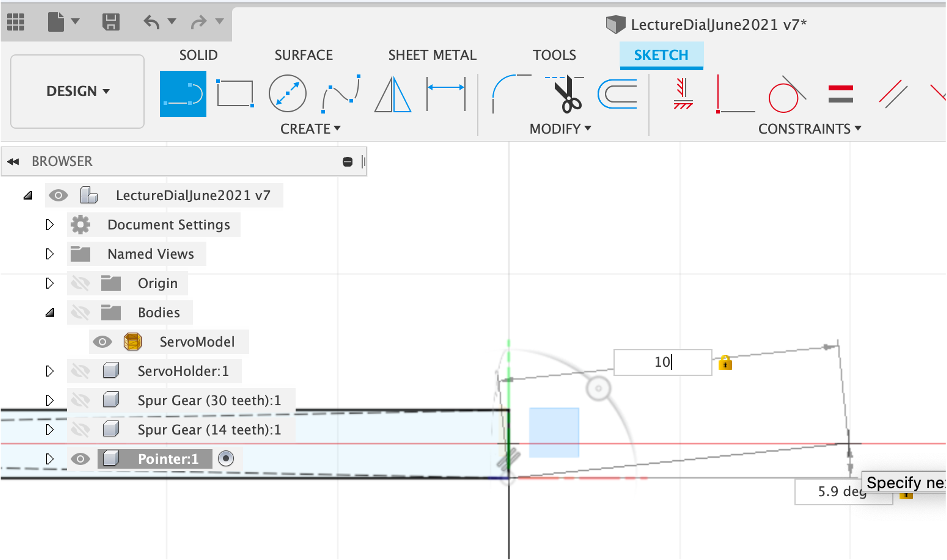
Go to Create and Line - Note there are various line types, including Construction Lines, which are useful as guidelines for projects. For now we are going to use the standard Line option.
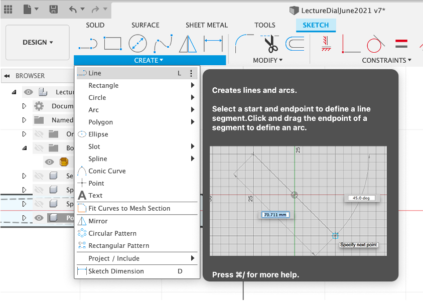
Select the botton point and hover over the red line to snap. Type in a length - 10mm and draw another line to close the triangle.
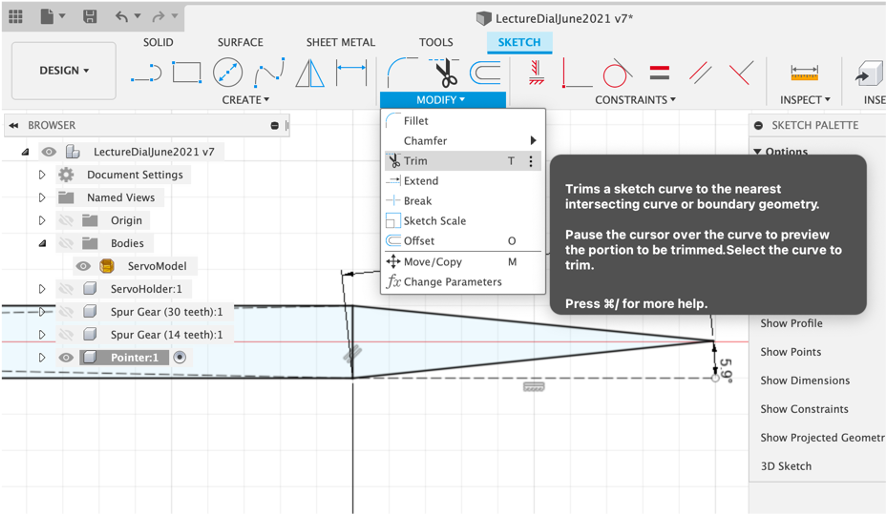
Select Tool - Trim - (t to shortcut) and Trim the 90 degree end line.
The Trim tool is useful to clean up sketches.
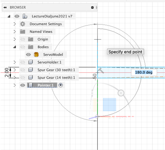
Zoom into the opposite end of the Pointer and go to Create - Arc - Centre Point Arc.
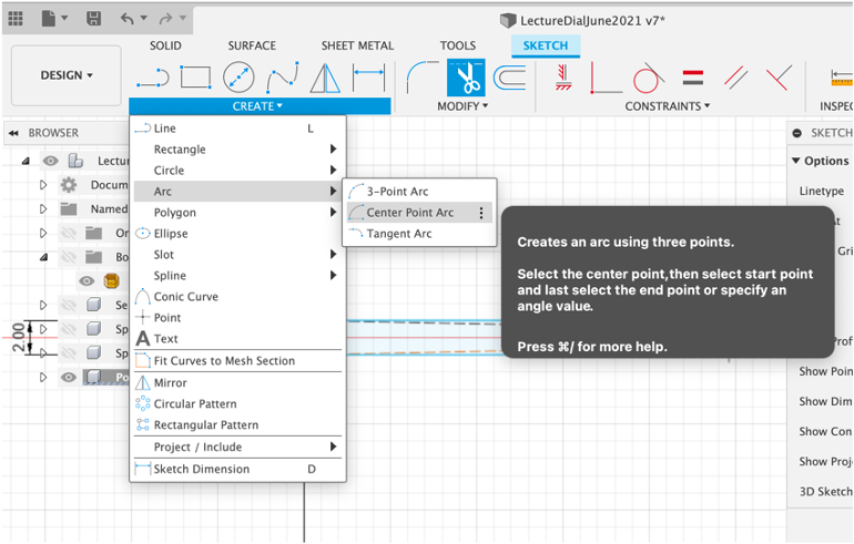
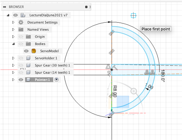
Click the Centre of the end of the pointer and drag out create an arc, set the size - 8mm. Drag it round 180 degrees to complete the arc.
Offset the line by 1mm and close the end using the line tool.
Use ‘Trim' to tidy up the lines and ‘Press Pull` by 1mm to create the extruded pointer.
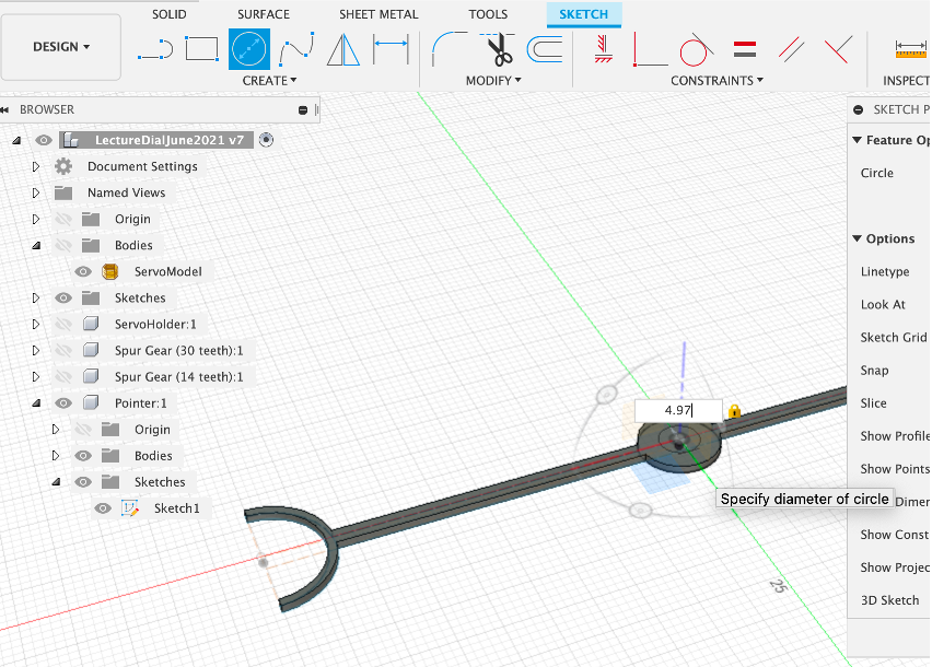
We now need to create a section on the pointer so it insects with the Gear. Create new Sketch and a Centre Point Circle of 4.97mm. We know the Gauge Gear has a 5mm holder, 0.3mm clearance allows a push fit.
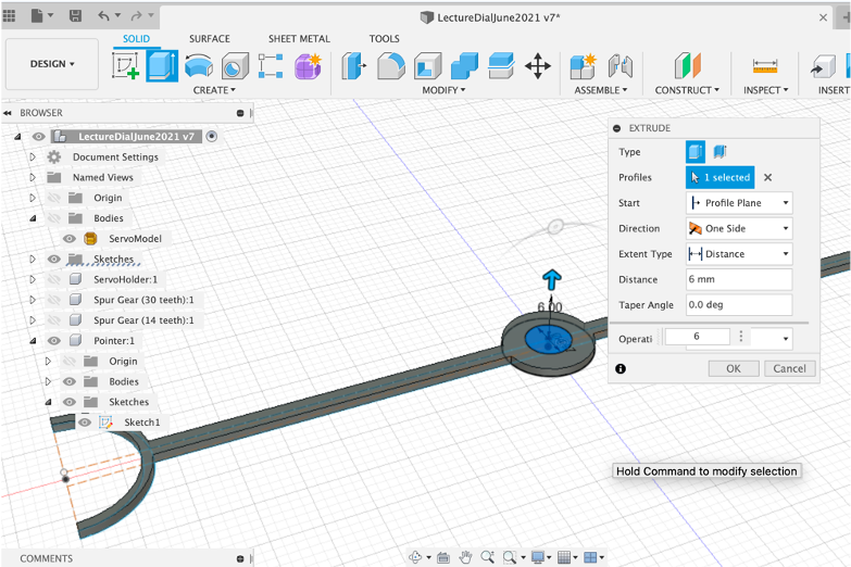
Press/Pull by 6mm - this will push into the Gauge Gear
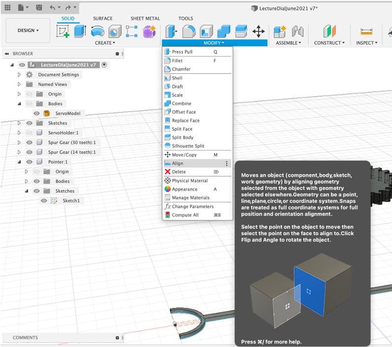
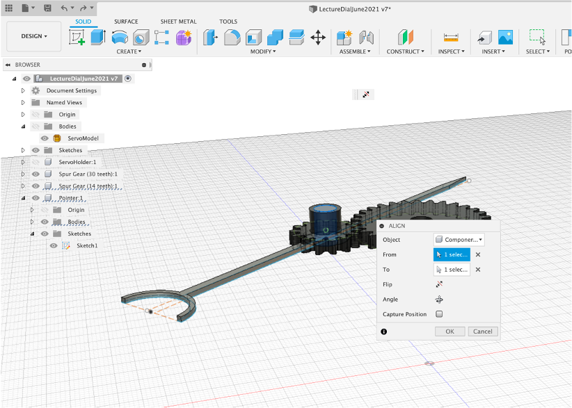
We now want to align it in place - select Modify - Align and Select the Centre Point of the Pointer.
Select the top of the Gauge Gear - the Pointer will snap into place (although upside down)
Select Move and ensure the Pointer is selected.
Rotate and move the Pointer into place.

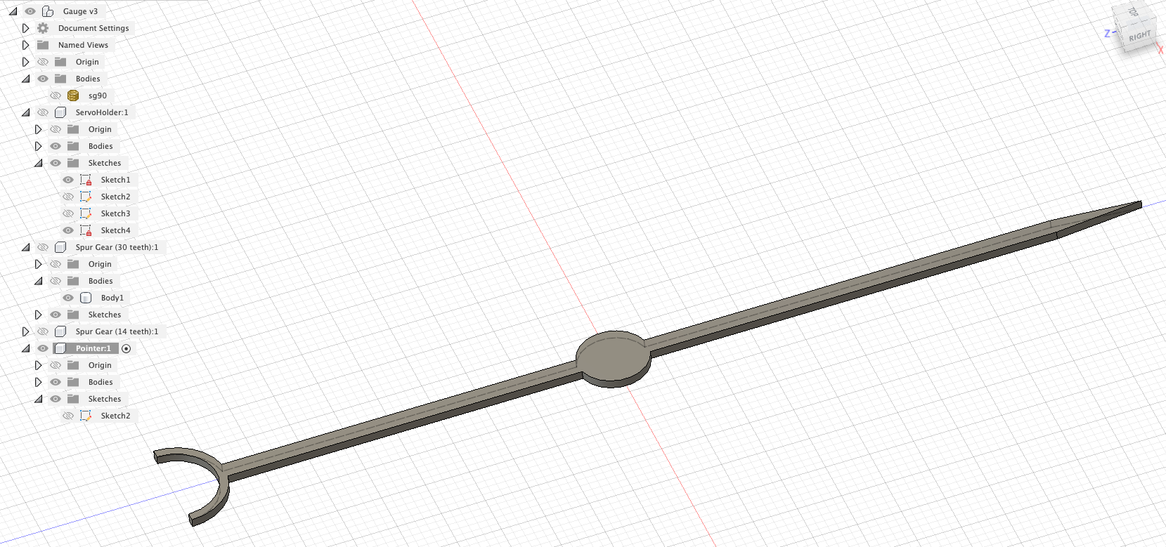
You now have a completed Servo Holder complete with a Gear Train and Pointer. We have covered the following concepts in Fusion 360 to reach this point:
- Lines
- Arcs
- Trim
- Components
- Sketches
- Offset
- Fillet
- Projection on Face
- Press/Pull
- Cut
- Spur Gears
- Importing Mesh
- Capture Position
- Visability
- Rendering

We will reuse all of these concepts and add some more to make the rest of the Gauge.
Animation in Fusion 360 is both powerful and a little useless at the same time. For this reason in the module we explore animation in both Fusion and Blender, Fusion 360 is however useful for rendering the ‘making' of models. At the present time Fusion 360 does not export any of its animation or render it using the built in render engine (!)
Despite these caveats it is a useful part of the toolkit to know.
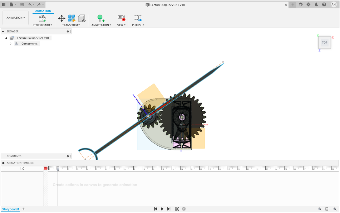
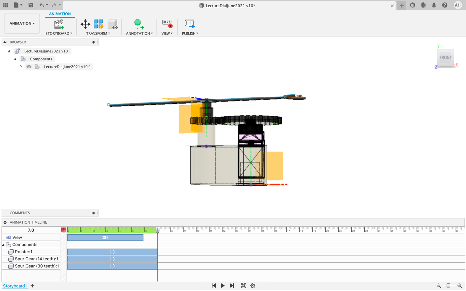
Camera movement is automatically recoded and added to your animation timeline. These timeframes can be quickly moved and resized allowing the basic concept of Move/Rotate and then adjust the time slide to be a quick way to create animations.
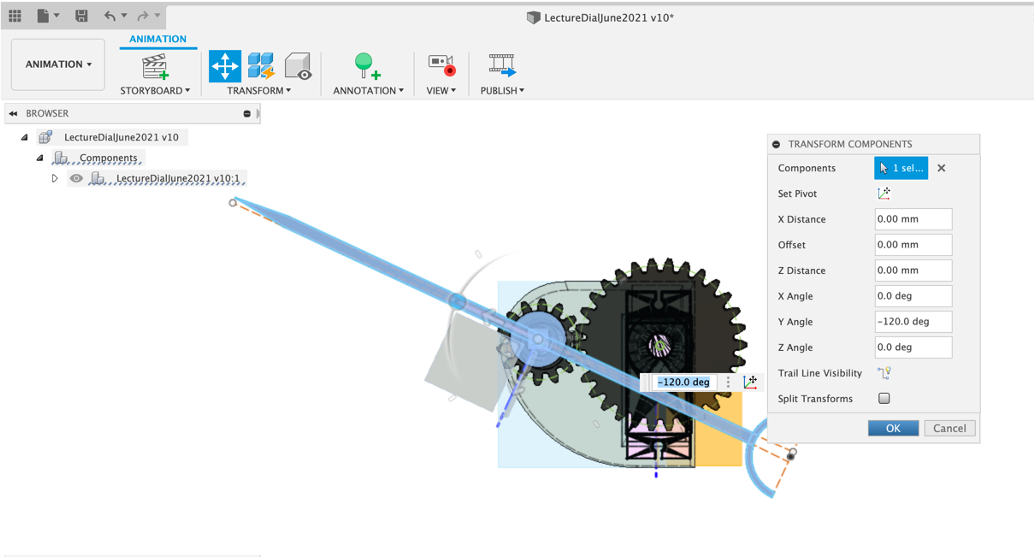
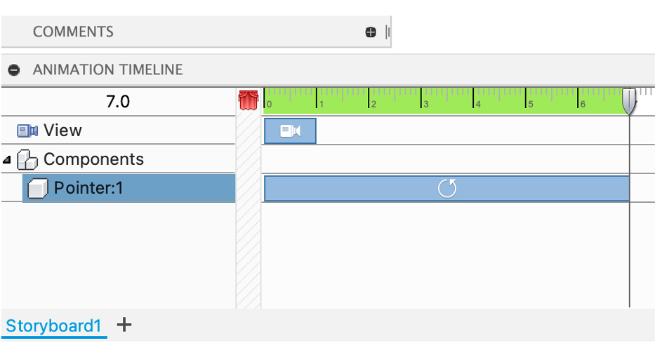
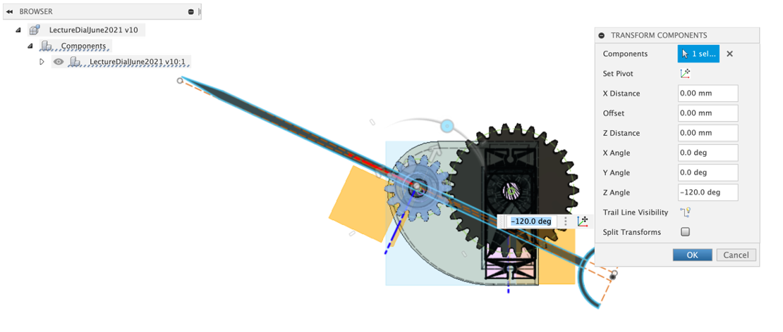
To illustrate this - selected your Pointer and Transform it 120 degrees.
A Timeslider appears in the timeline - this can be moved and resized.
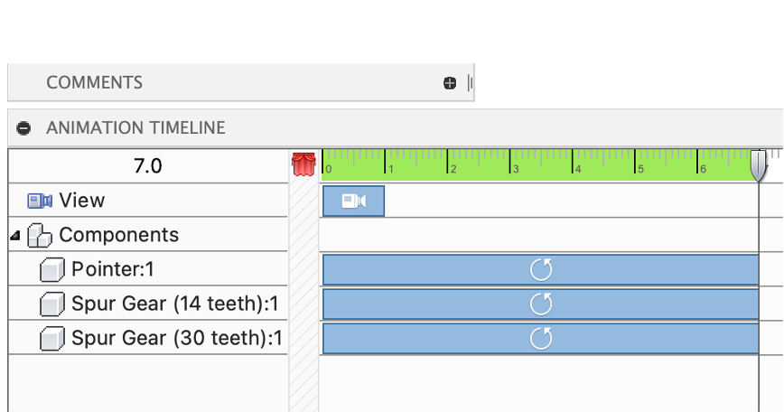
Select and Transform the Gauge Gear - again rotate by 120 degrees;
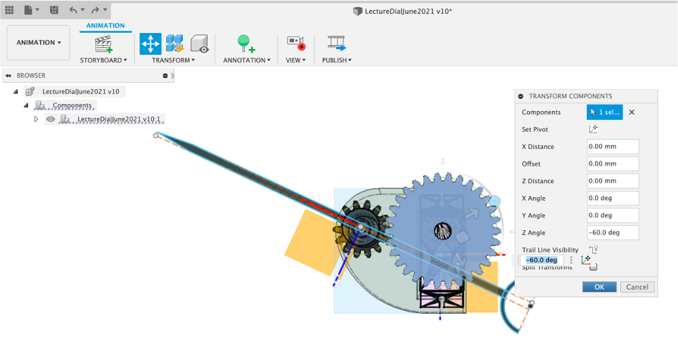
Carrying on the theme - Select and Transformthe 30 Gear -60 Degrees (this is approximate) - ie mimicking the movement of the gears
Tweak and line up the timelines so they both move at the time
Move the Camera to a side view - Note - a new camera movement is created everytime you move it.
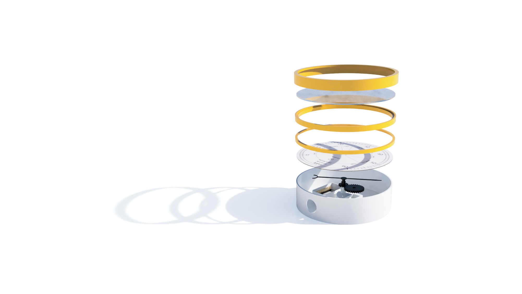
Select and Transform the Pointer to a new position - ie above the servo holder as pictured below.
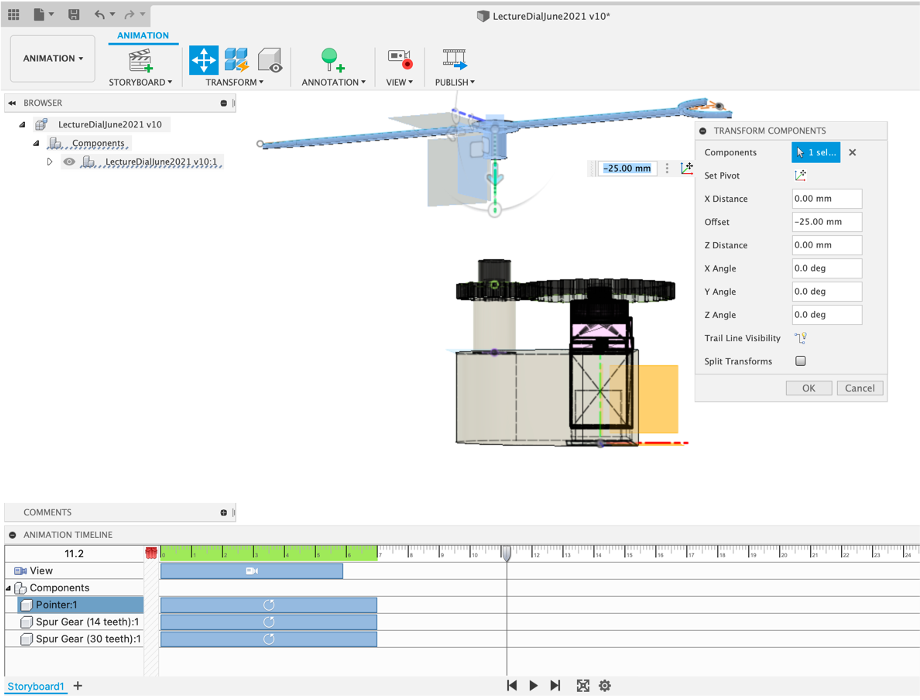
Repeat with both the Gauge Gear and the 30 Gear.
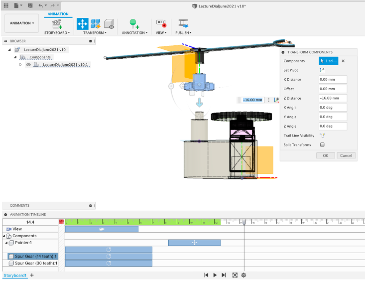
Repeat in Reverse to move them back home - Fusion does have a Restore Home function but at the time of writing it is problematic.
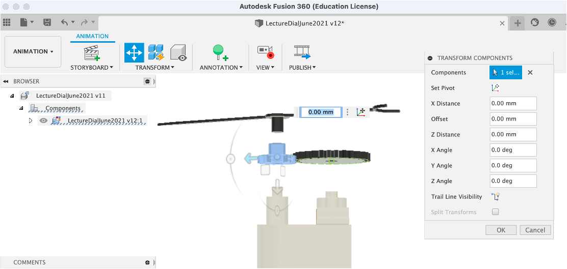
Move the camera to a final view and alight your time sliders - this takes a little practice.
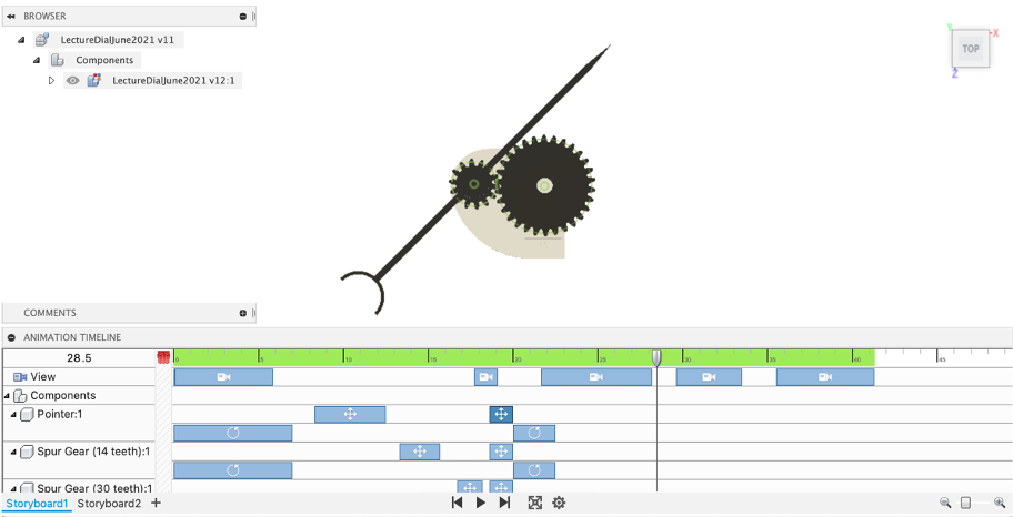
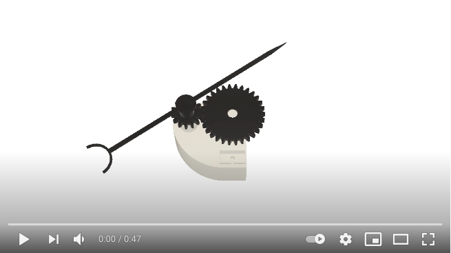
You should now have your own version of the animation below:
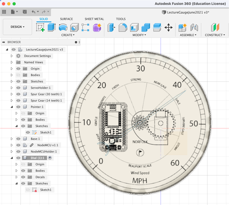
We now have many of the key concepts in Fusion 360 covered, we are going to use these techniques to quickly build the Main Gauge - the main features we need to think about are:
- Size - the Gauge can be any size, limited only by the torque of the servo and the size of the print bed. Here we are going to use a size of 150mm as its a good comprise between a useable guage and print time. In a perfect world you would use a slightly larger size, to make use of the full print bed.
- Does Gauge have a front cover - glass/acrylic?
- Does it need lighting and if so how is the lighting used so it is a soft diffused light keeping with the power limits of the Node MCU board.
- The Gauge needs to hold the Node MCU along with our Servo Holder with access to the power supply (USB Cables).

Additional concepts covered include
- Change Camera Type
- Importing from the Fusion 360 Gallery
- Using Decals
As with all 3D modelling, there are no right or wrong methods, merely many ways to reach the same end point. In the next steps we will be offsetting, pushing and pulling to create holder for the main components as well as ridges to hold both the dial and the acrylic. It looks perhaps overly complex at first but once the techniques are in place such a model can be made and ready to print in under 30 minutes.
Acrylic discs make a perfect material to use for the front of dials, they are lightweight but provide both protection and a certain look to the device. In addition they can be used to ‘tap' onto if you add in a vibration sensor - perhaps to trigger the showing of a High and Low data reading for the day. This harks back to the days of tapping a barometer as the pointer would often get stuck on small movements.
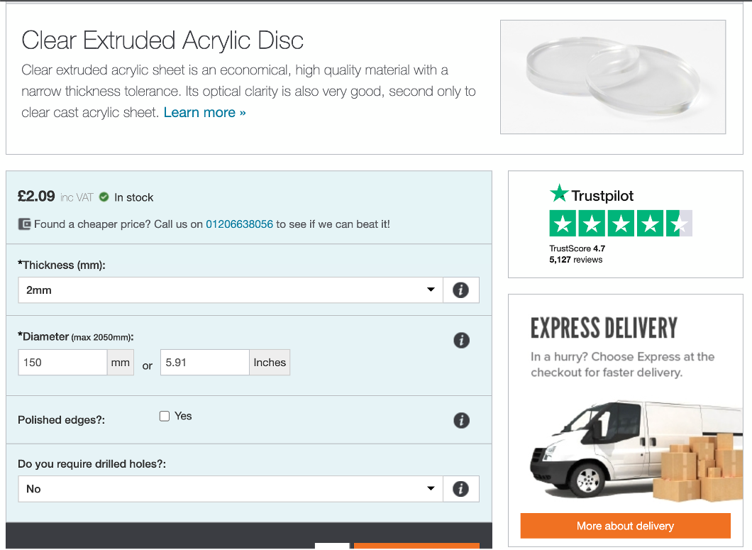
Simply Plastics is a great side for all things plastic and they provide a number of options on Acrylic discs.
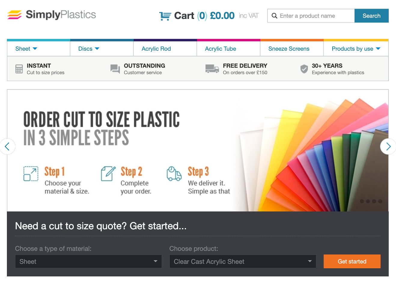
For our set up we used a 2mm thickness with a 150mm diameter - delivery time is approximately 5 days
Or of course - explore cutting your own at the Bartlett Workshop.
Start the base by adding a New Component, name it and then Create Sketch and create a Centre Circle of 150mm
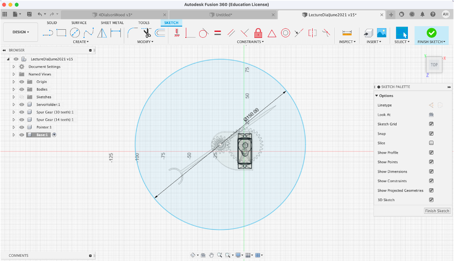
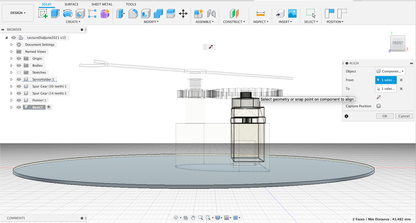
Press Pull 1mm and then Align - Select the bottom of the base and the bottom of the Servo Holder.
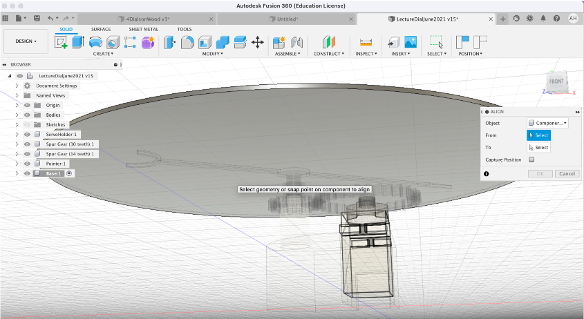
You scene should look similar to the image below:
Select the Bottom Edge of the base and Offset by 2mm - This is wider than our normal size wall, to hold the Acrylic.
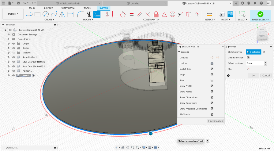
Select the Front View and Change the Camera to Orthographic.
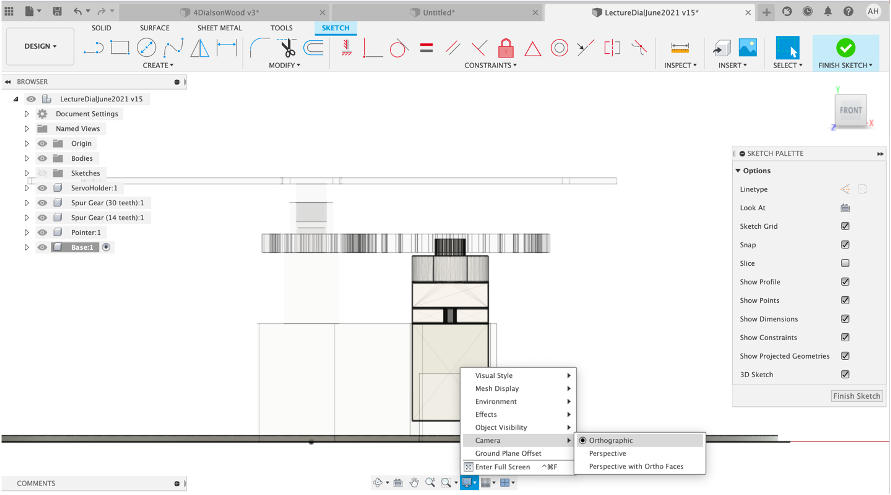
Rotate the Camera View to select the offset plane - switch back to Front View and Press/Pull -40mm - This pulls the side up just above the Gauge Gear - this is where the Dial will Sit.
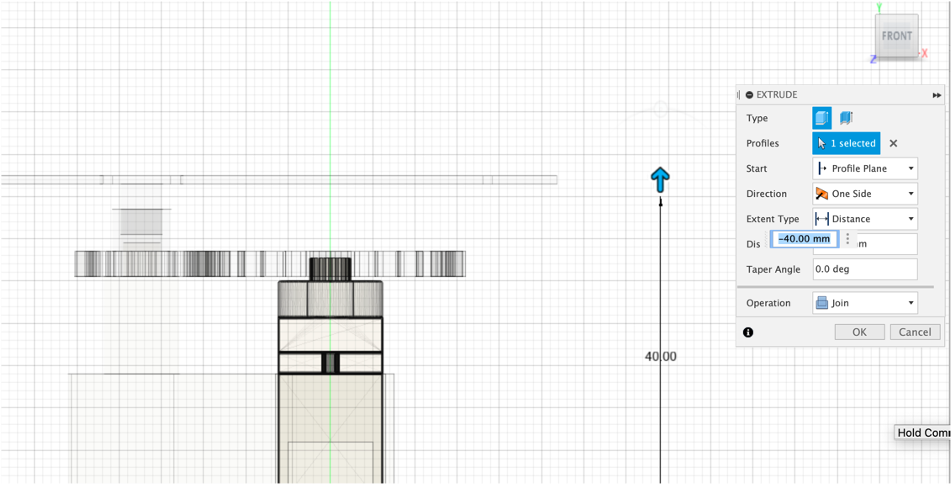
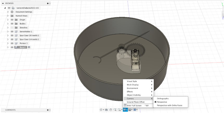
Change your Camera base to Perspective - you now have the base in place.
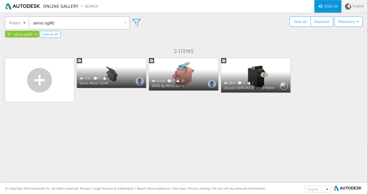
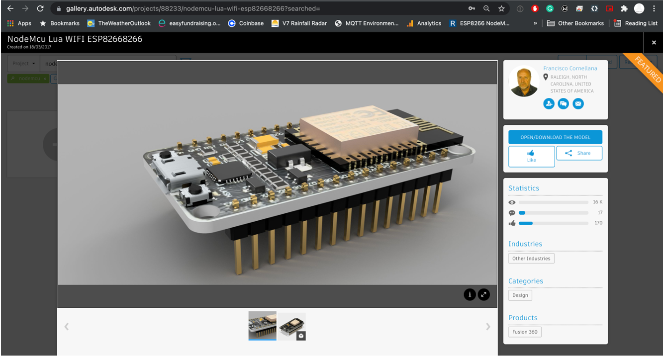
The Autodesk Gallery contains models from Fusion 360 users. As with the import of any model the dimensions may not be true to the physical object, however due to the nature of Fusion, the models in the gallery are more trust worthy than other sites.
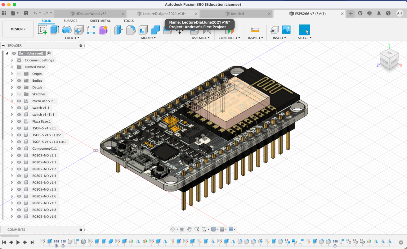
Either open the Autodesk Gallery and search for Node MCU, download the model - note you will need to be logged on with your Autodesk account. Or get the model from our ‘Essential Files Folder' (ADD in LINK to NODEMCU MESH)
Open a new tab in Fusion (for a new model) and File Open Open from Disk
Now simple Save the model and it becomes part of your collection of models, available to import into any design. It is worth building up a series of models for import - ie Raspberry Pi's, LED's, Servos etc for use across future designs.
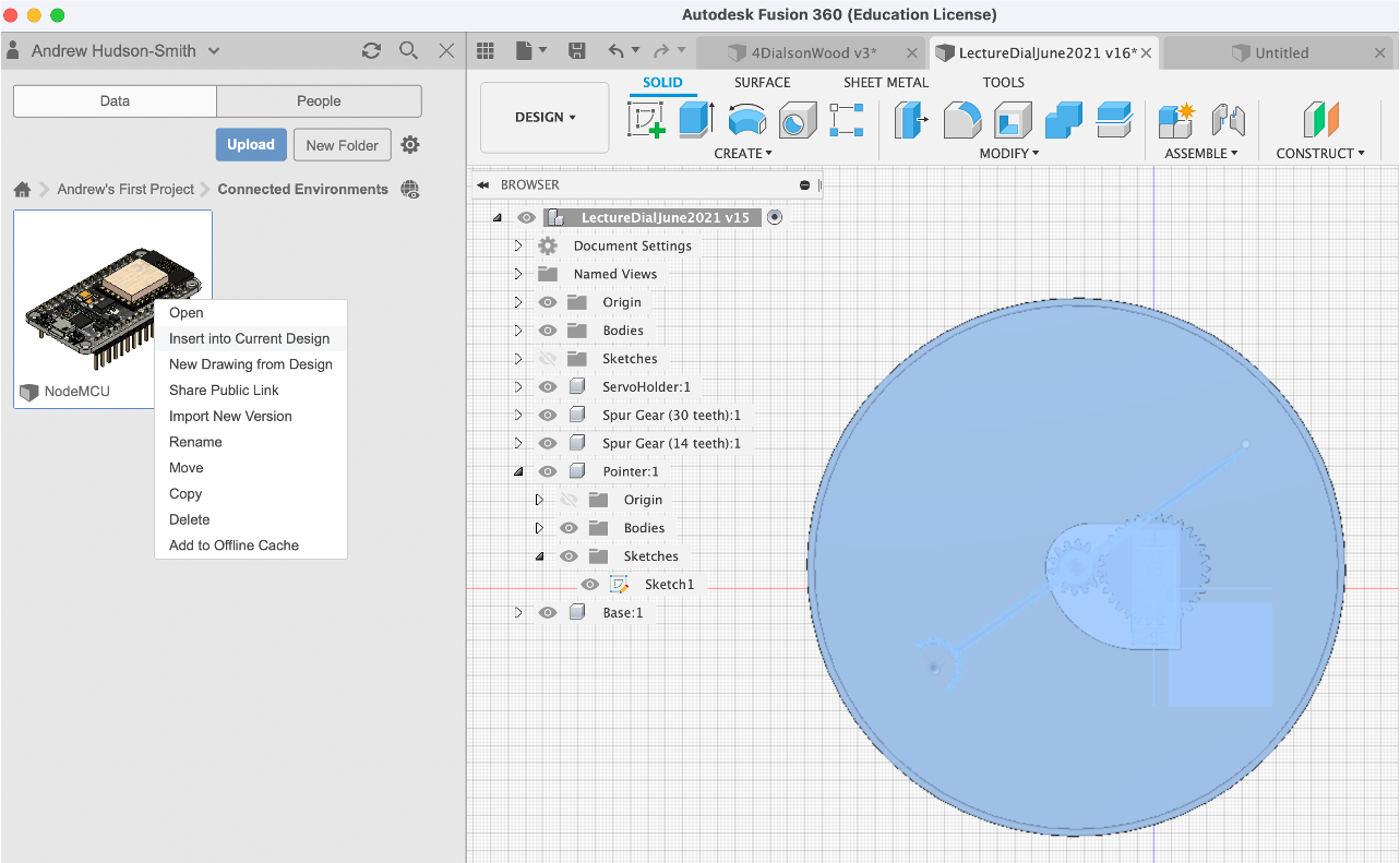
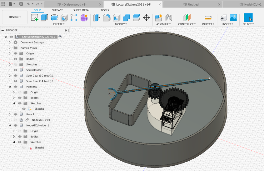
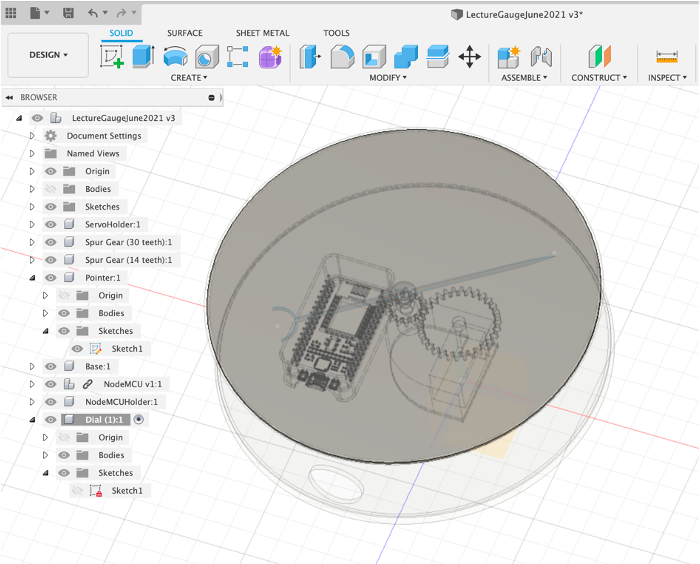
Go back to your Gauge and import the NodeMCU - highlight the parent first and then right click on the NodeMCU and insert into current design.
Move/Rotate the NodeMCU so it sits just above the base and just off centre.
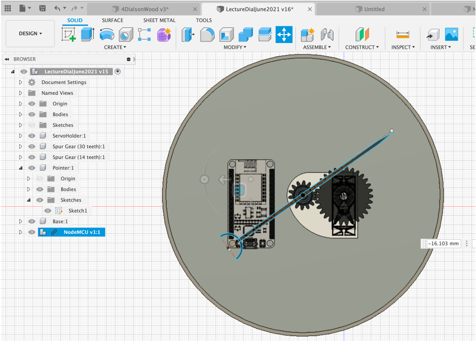
In the next steps we will use the model to create the main NodeMCU holder.
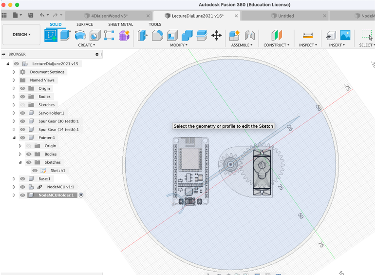
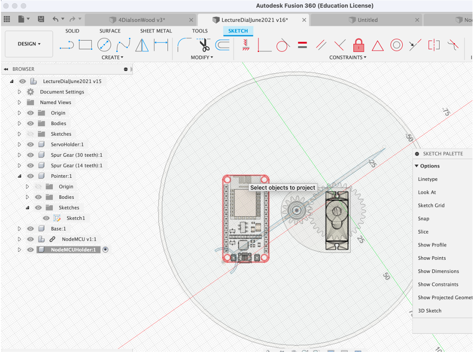
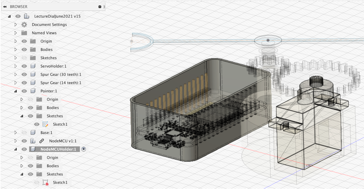
Using our now standard workflow - New Component name it NodeMCU Holder, Create Sketch. We are going to use the Project function to take the dimensions of the NodeMCU model and Project them onto our Sketch. Create Project/Include Project and select the outline of the NodeMCU.
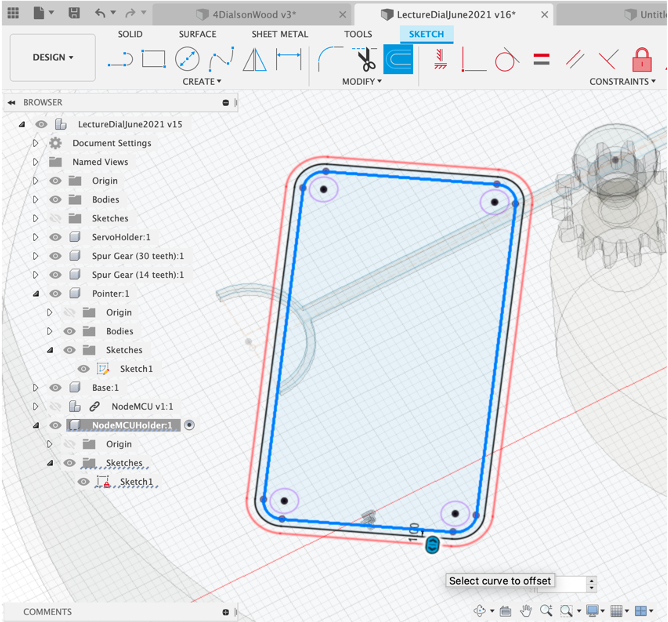
We will now offset to create the main part of the holder - Offset (o keyboard shortcut) by 1mm
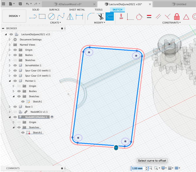
Repeat the offset - this time 2mm - this makes a wall 1mm from the NodeMCU.
As in previous steps we now use Press/Pull to extrude the outline. Select the Offset and Press/Pull - 18mm. 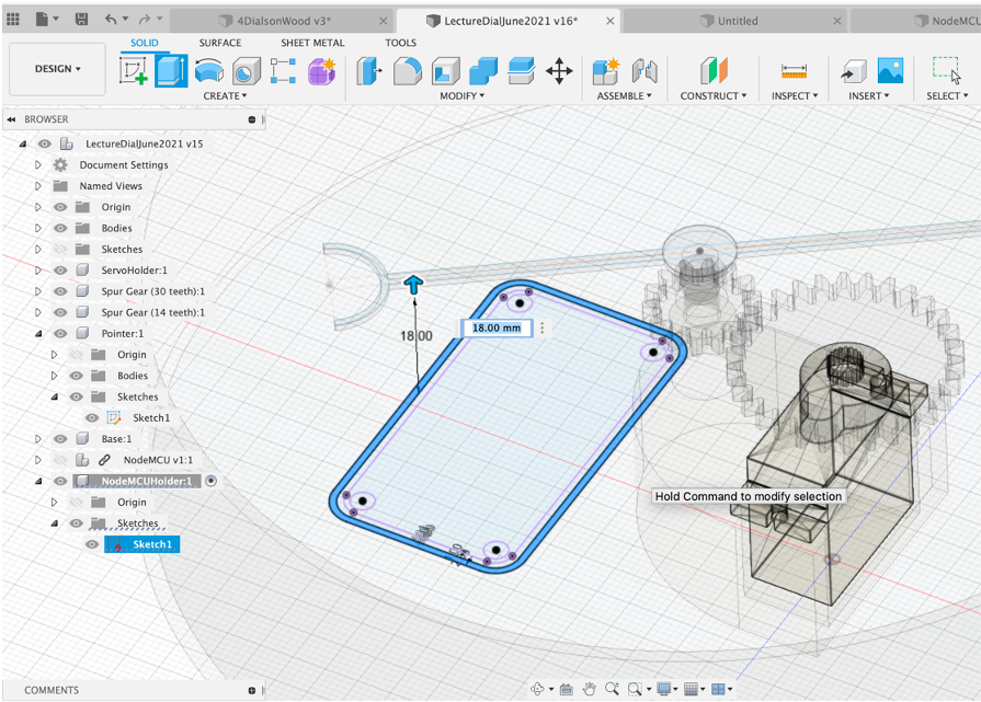
This is large enough to hold the NodeMCU with its connections.
We now need to create an opening to plug in the USB cable. As ever with Fusion there are multiple ways this could be completed - you could draw and new sketch and Press/Pull a shape to cut a hole. Or us the Hole Function.
To use the Hole Function simple select the Hole icon and click the front face of the NodeMCU holder.
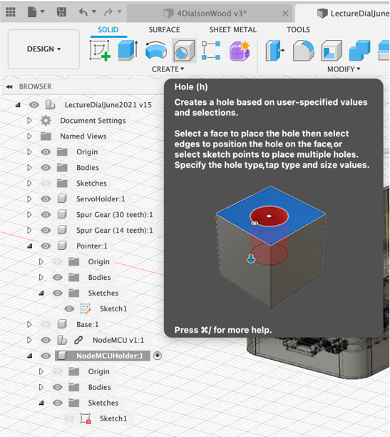
Cut a hole of suitable size.
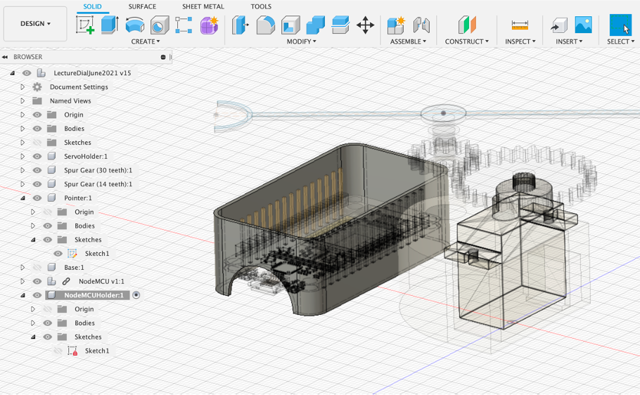
We also need a hole in the base for the USB cable - approx 22mm. Note the hole may need to be rotated before cutting, to align with the bottom of the Gauge.
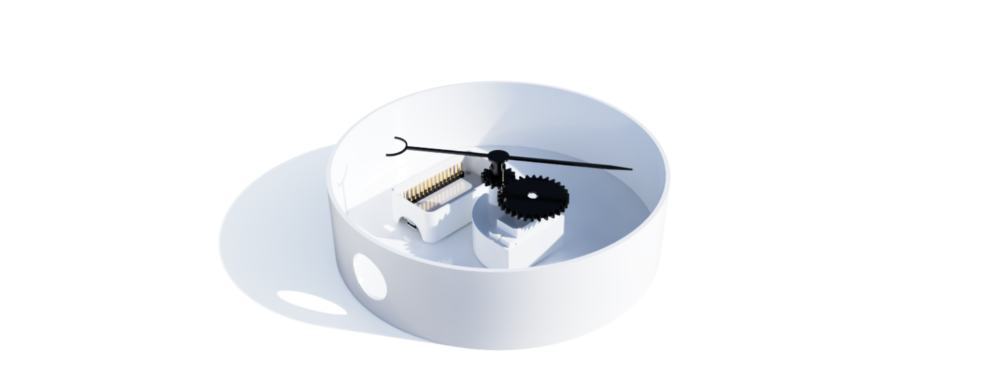
You now have a complete Base and NodeMCU Holder - your gauge will now function - although it needs a dial, perhaps some lights and a few components to hold the front cover in place.
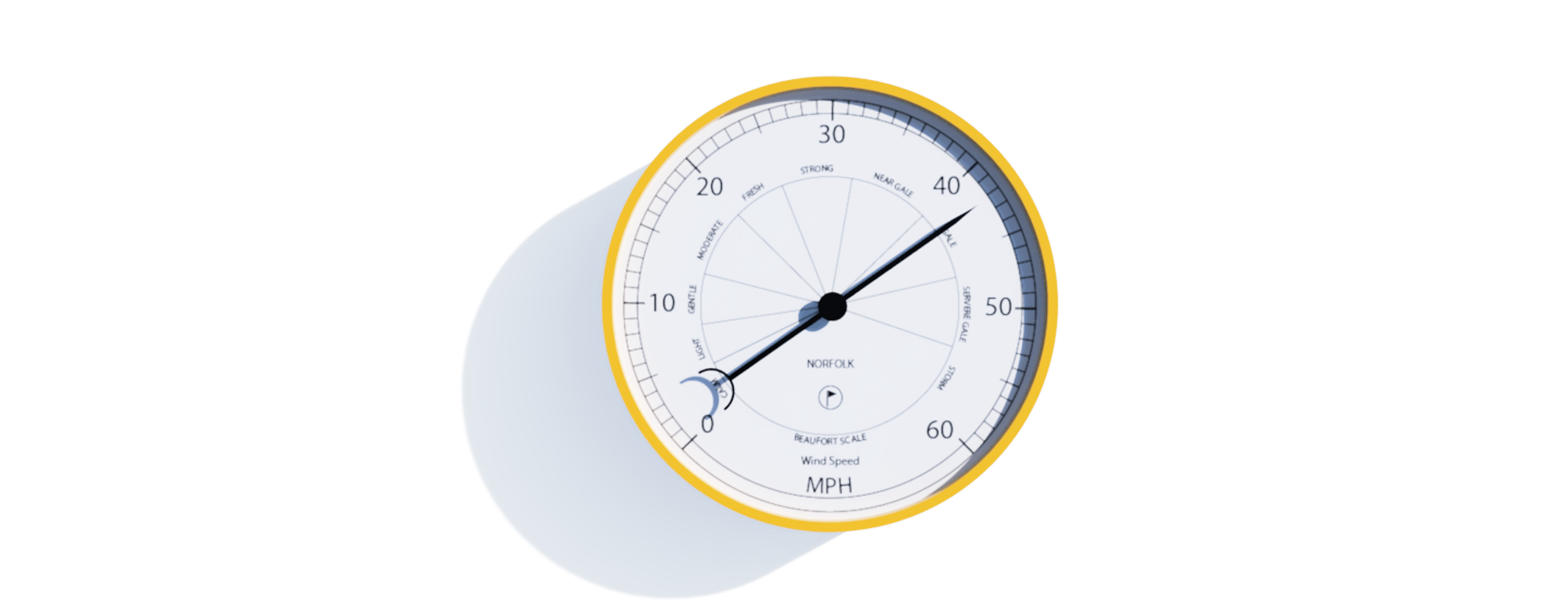
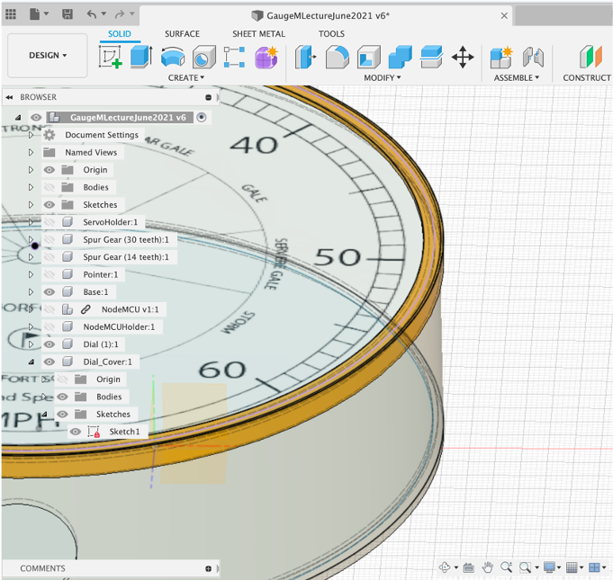
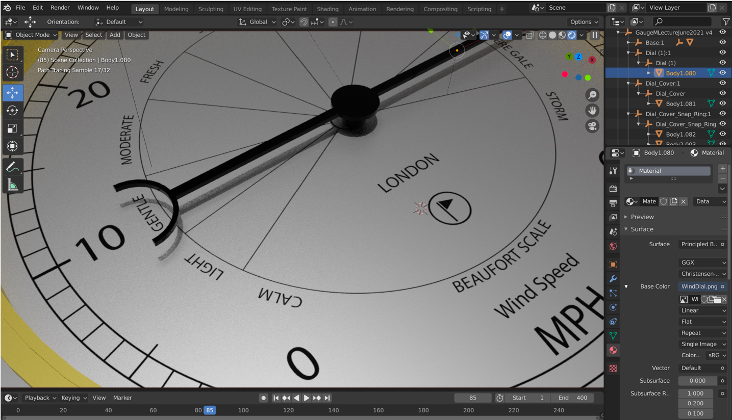
The Dial is interchangeable - because our Servo allows a 360 movement it can be adapted to any data you want to use. The dial was made in Adobe Illustrator, although any Vector package could be used. In this section we use the Fusion Decal function to import and place a texture while also creating the physical dial holder.
Create a New Component, name it Create Sketch - `Central Diameter Circle - 152mm.
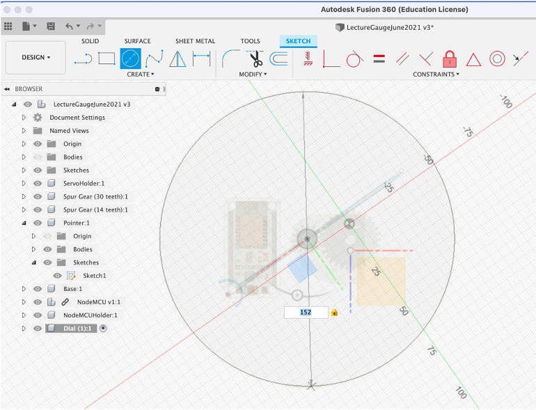
Press/Pull 1mm - this give us a base for the dial.
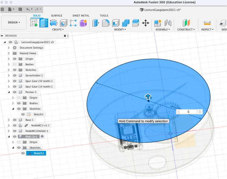
Move the Dial into place - just below the Pointer. Adjust the pointer up 1mm if required, so it sits above the dial.
To insert the Decal - Insert Decal From my Computer and locate winddial.png.
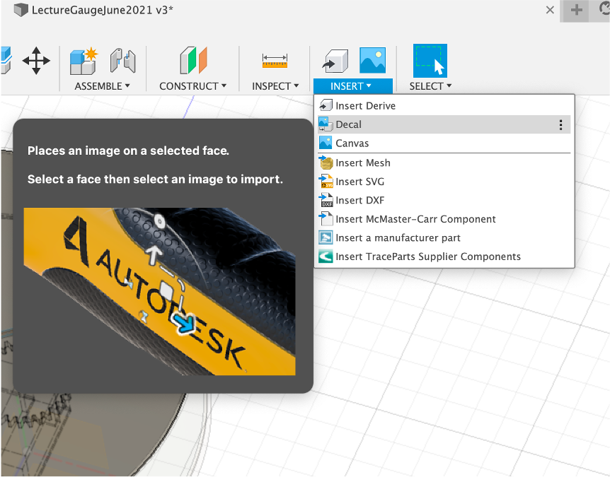
Select the top face of the Dial to place the image.
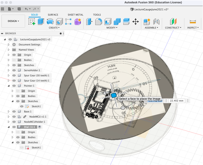
Move/Resize/Rotate until the image is centered and lines up with the face.
You now have the dial in place - the dial base is used later to 3D print using a Translucent PLA, enabling a paper dial to sit flat in place while also letting light shine through.
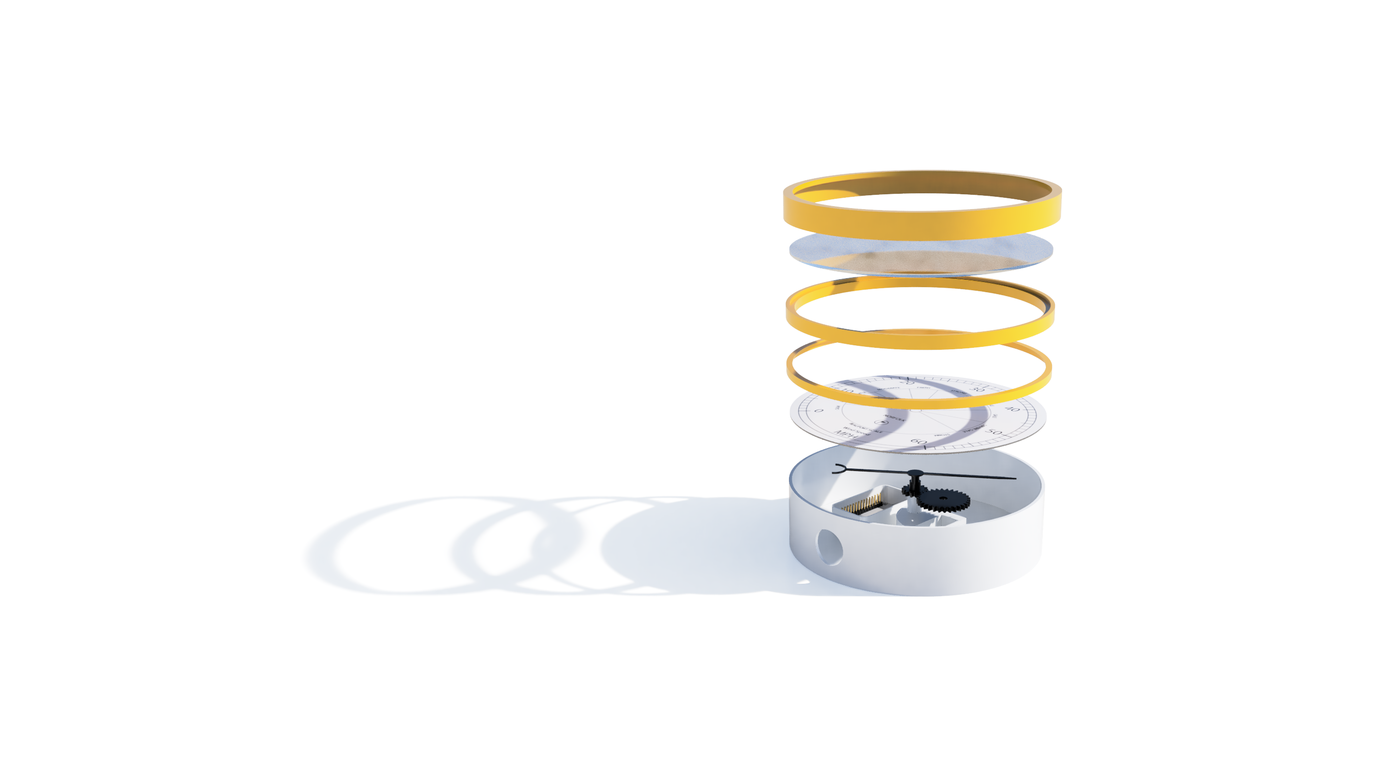
Acrylic Front/Rim/Cover
We now need to make a series of components to hold both the Dial and Acrylic disc in place. It should allow easy access to disassemble the Gauge, while also being hinge and glue free.
Dial Holder
Our first new component is a Dial Holder this holds the paper printed dial in place and secures the dial translucent base to the main gauge - New Component - name it ‘Dial Holder' - Sketch - Centre Circle. 154.5mm - this is slightly wider than the main base (as it will fit over it). We now need an outer rim to then extrude down - Centre Circle 155.5mm and an Inner Rim - `Centre Circle 148mm'.
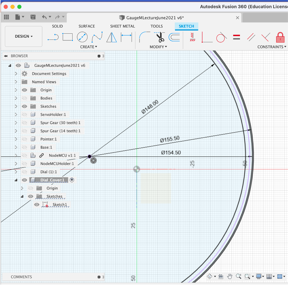
We Press/Pull the outer rim by 5mm and the Inner Rim by 1mm - creating the component as pictured below.
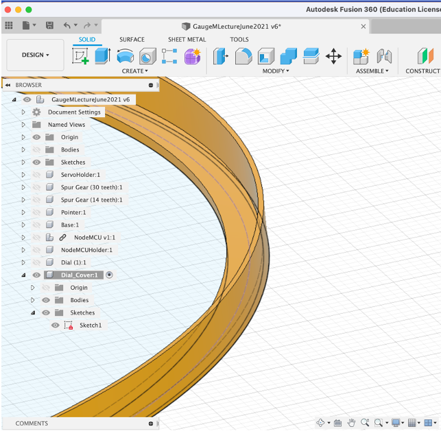
This will fit over the base and hold the dial in place.
Acrylic Holder
We now need a similar component for the Acrylic - which needs to sit above the dial with enough space for the Pointer to freely rotate. It is for these type of details that a pre sketch drawing is often useful.
As before - New Component - Rename - Sketch Centre Circle:
154mm - the size of the outer rim; 150.5mm - .5mm wider than the Acrylic and; 144mm - creating a ridge for the Acrylic to sit on.
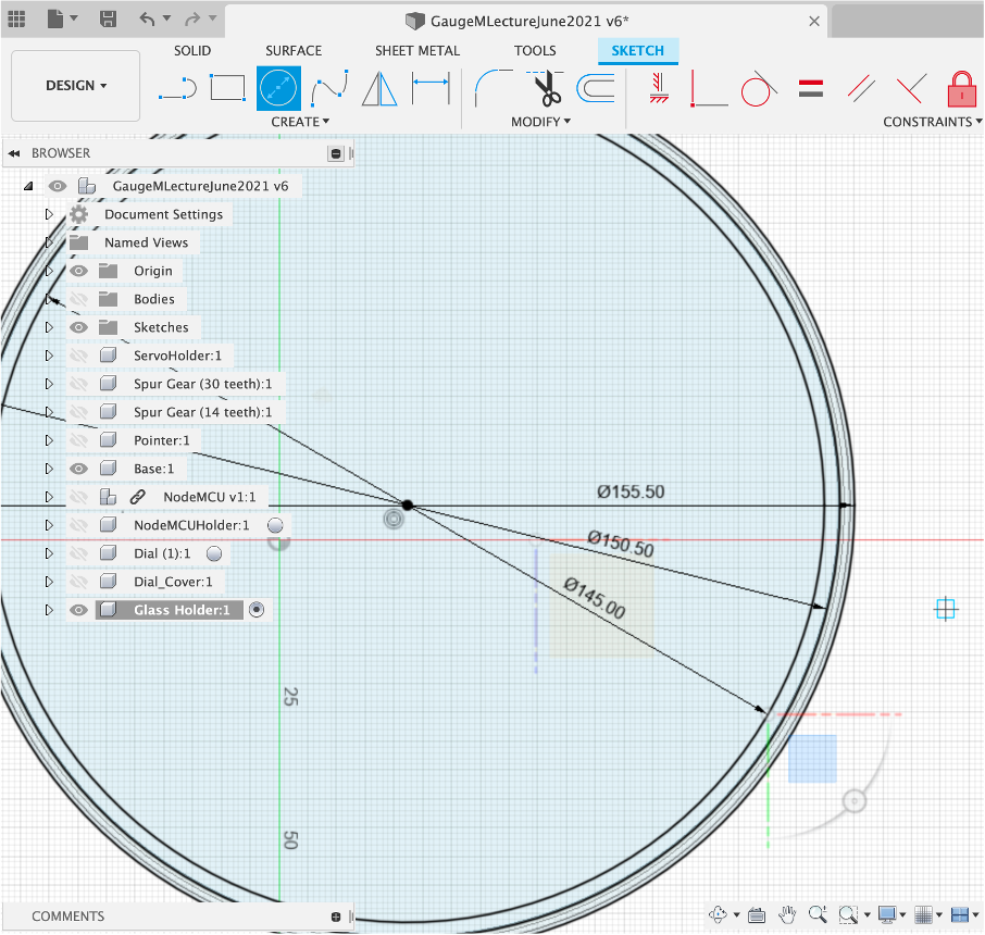
‘Press Pull' the outer circle by 8mm and the Inner Circle by 6mm - this provides the 2mm gap for the acrylic.
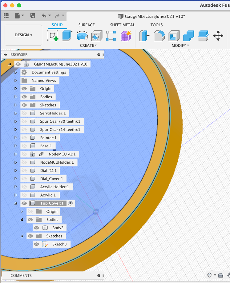
Top Cover
Finally (almost) - The Top Cover holds everything in place and provides a clean look to the Outer Rim. As before - New Component rename Sketch Centre Circles:
156.0mm - .5 larger than the Dial Holder 157 mm - a 1mm outer wall 140.0mm - the inner rim
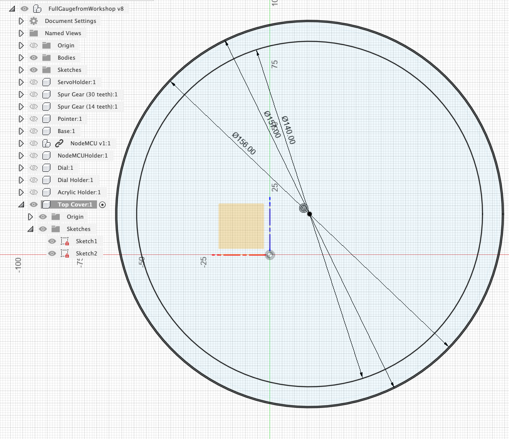
We now 'Press Pull to create the final part of the top cover:
Press/Pull 1mm for the inner rim and 14mm for the outer wall. This slides over the other sections while the inner rim holds the Acrylic in place and frames the dial.
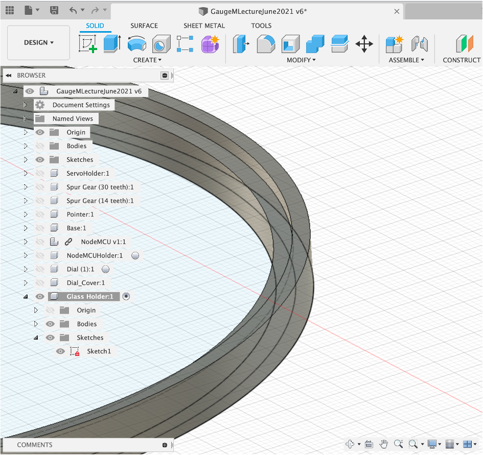
The Virtual Glass
The physical object uses the Acrylic disc, for the digital version we need to simply create a new disc and assign it a glass material.
New Component - Rename - New Sketch - Centre Circle 150mm (the same size as the Acrylic).
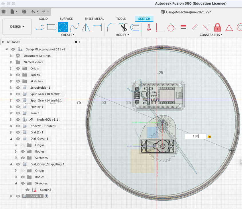
‘Press/Pull' 2mm and move into place.
A final part of the main base, before rendering the glass, is to cut a hole for the USB lead -
You could also cut a hole in the back so the gauge can be hung on a wall.
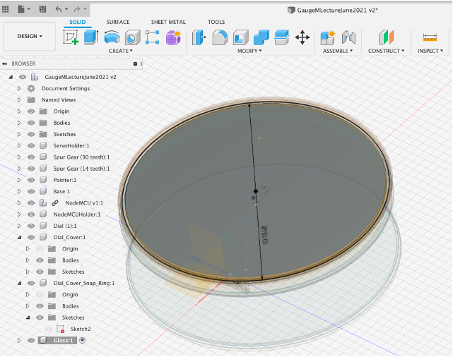
Finally - To assign a glass material - Render Appearance and Search for Glass.
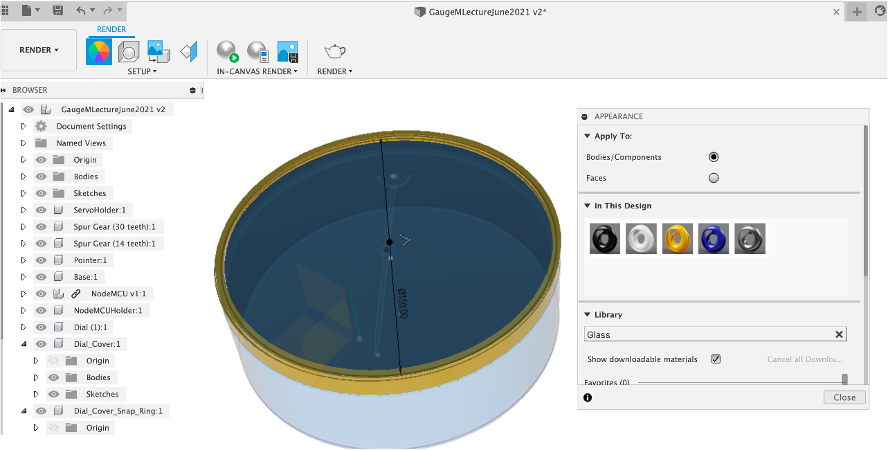
Render the Scene:

Fusion exports in a variety of formats - .fbx is arguablity the most flexible as it allows import into almost all other packagages while maintaining its hierarchy. All files are exported via the cloud and take longer than they would locally.
To export a file, simply File Export FBX. The export in Fusion is however slightly underwhelming, no textures or animations export with the file.
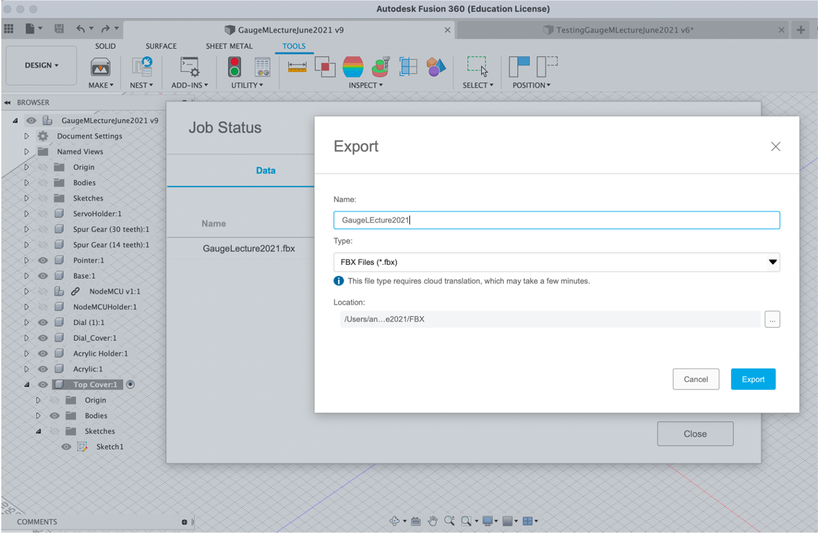
We solve the lack of animation and texture export in the follow up lecture by importing the model into Blender, Sketchfab and Unity.
Technical Drawings are a key part of Fusion, they update dynamically on any file changes and provide a key way to provide size and location details of your model.
To create a technical drawing simply go to File New Drawing From Design note the options on sizing etc. This process opens a new window and interface.
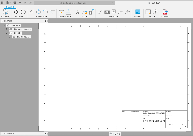
Views are added by creating and dragging (which is slightly counter intuitive at first). Click Create and Drag out a Base Line view. You can change the View/Style/Scale etc in the dialog box - wireframe works well for technical drawings.
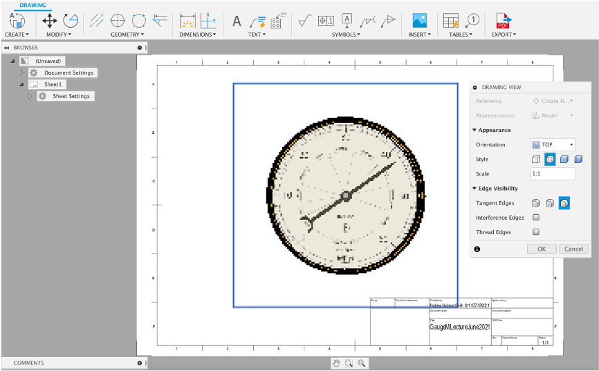
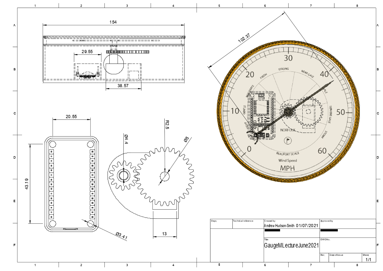
The interface is quite self explanatory - Dimensions allows you to click and drag on objects to show the dimensions etc.
You can click and drag new views to add top/side elevations etc - below details an example using the Gauge:
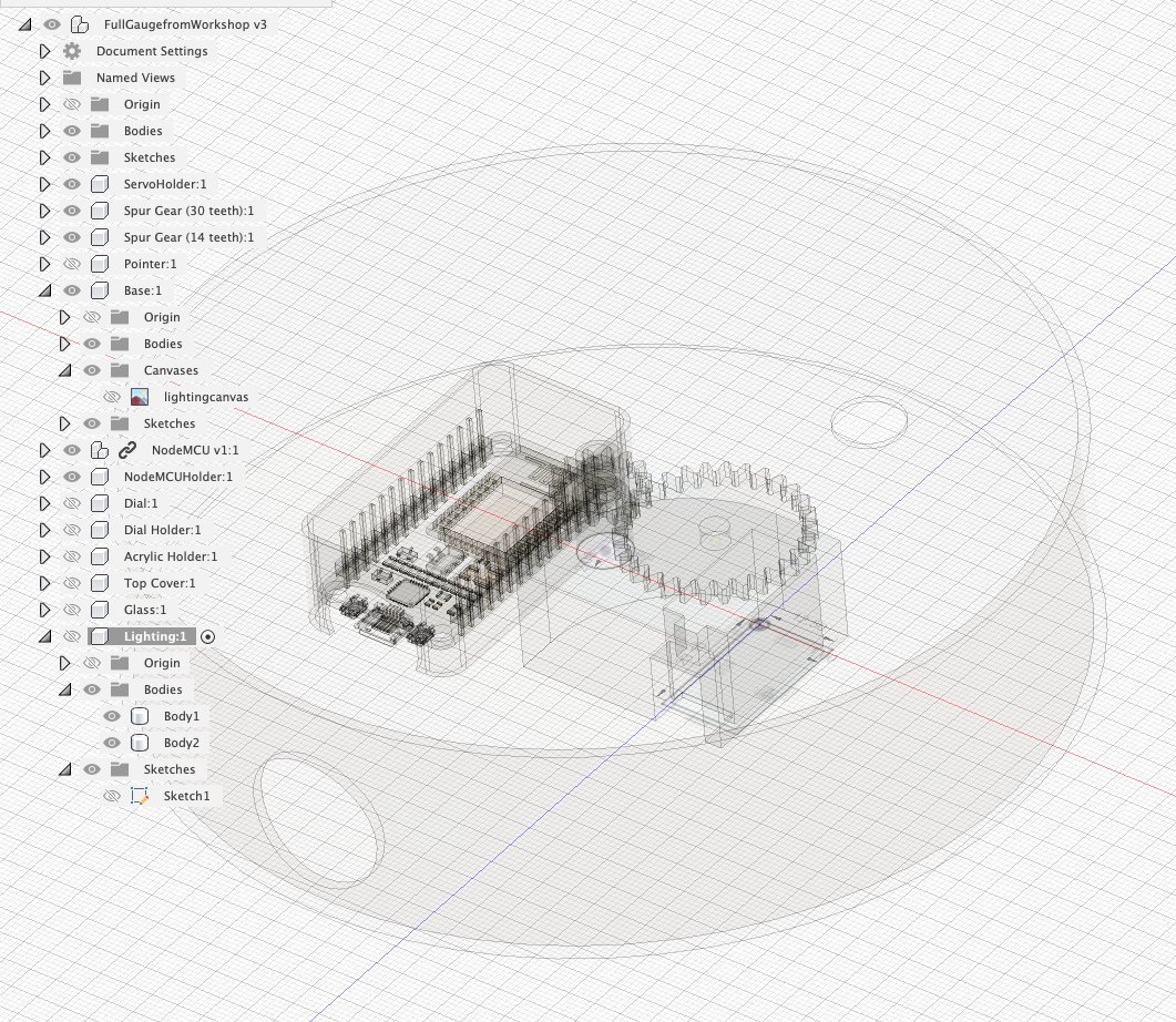
There is a story to this section - at first the lights were sourced from PiHut and all the sketches/canvas parts were in place, early June 2021. PiHut then discontinued the lights, only for Pimoroni to stock their own, but at slightly different dimensions, rendering this whole section of the workshop redundant. As such the sections below have been rewritten)....
Lighting adds an additional element to the Physical Gauge. Any low power LED's can be used but it is important to note that shining LEDs will create shadows from your wires, which will show on the dial. To limit these we have used two Pimoroini LED Backlight Modules. They provide diffused light and the NODEMCU is able to power two of them in addition to the Servo.
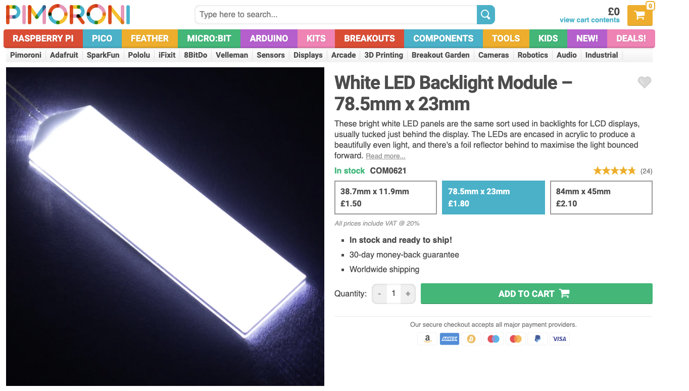
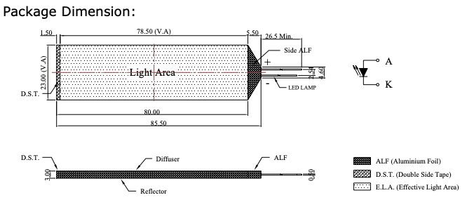
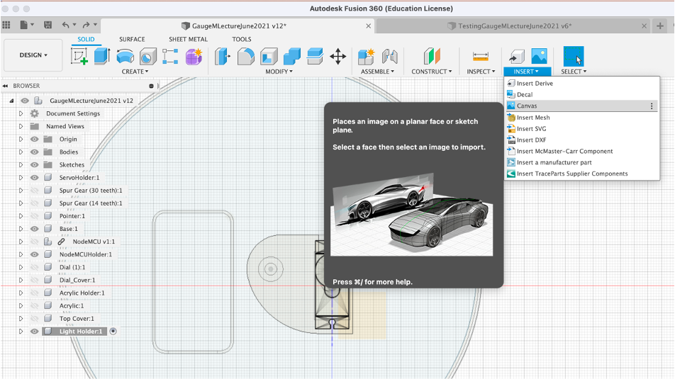
The Pimoroni page includes a downloadable spec sheet, we are going to use the ‘Canvas' feature of Fusion to import the technical drawing and use it as the basis of our model. It is also important to note here that although the product includes a technical drawing with sizes, there is no guarantee it is correct, calipers are always the best way to check.
Create a New Component rename it and go to Insert Canvas. Click on the plane to place and move/rotate until it is approximately in place.
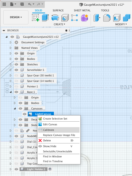
Note - the canvas needs to be calibrated before use.
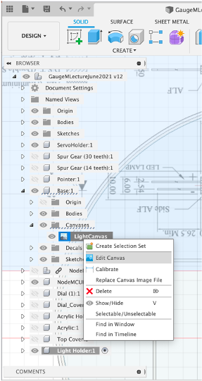
The Canvas feature is not placed within the component, it can be found in the main base hierarchy - Right Click and select `Calibrate'. Select the two width known points (marked as 80mm on the drawing.
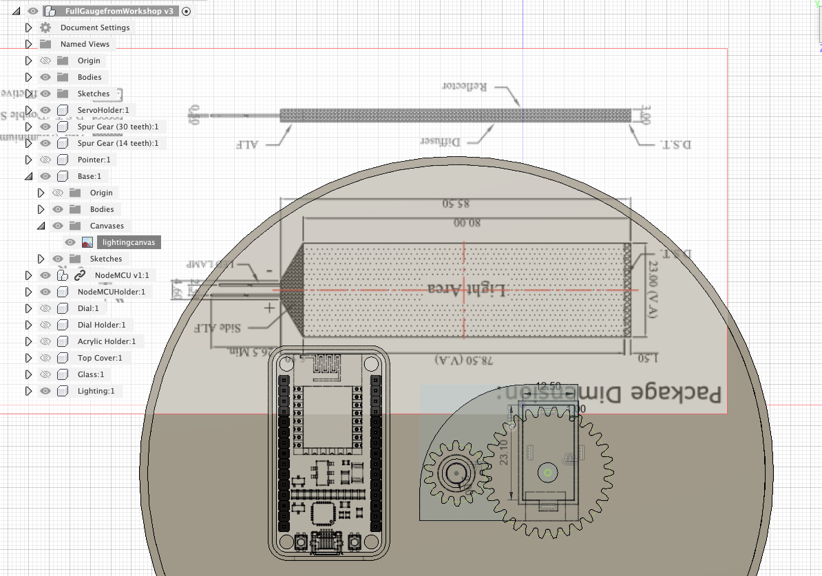
Now the canvas is calibrated we can move it into place - Right Click and Edit Canvas move it into place, it is now ready to trace over.
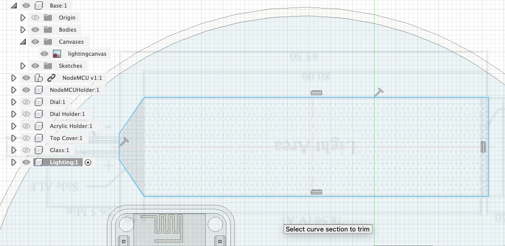
Create a New Sketch - make sure you are in your light holder component. Use Lines to outline the light area.
Once you have closed the lines Offset to 1mm to create a outline to hold the LED.
Offset again by 1mm to create an outerwall.
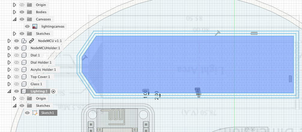
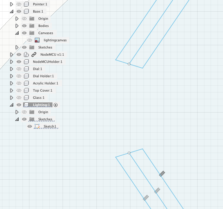
We need an opening for the connections - use the Line and Trim tools to close the outwall so we can Press/Pull but leave and opening at the end.
Your outline should look similar to the one below:
To Press/Pull you first need to turn off the Canvas Selection:
Select the outer wall and Press/Pull 3mm (the height of the LED)
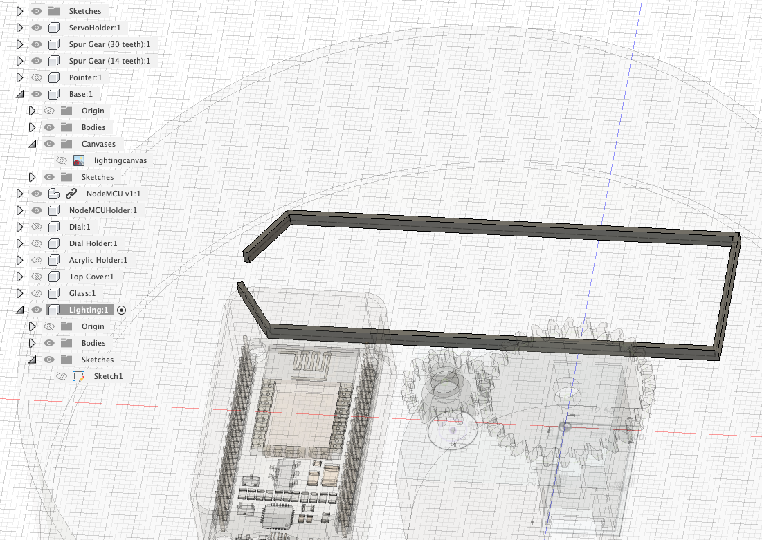
We need two light holders, so we need to make a copy. Select the body in the component.
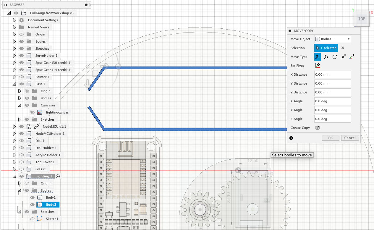
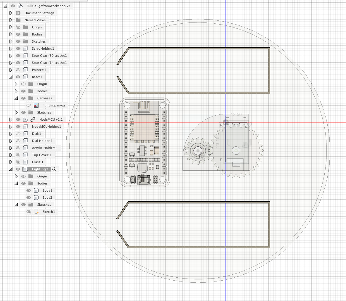
Select Move and at the bottom select Create Copy - now move the copy to the bottom of the Gauge.
Note the USB cable needs space to plug into the NodeMCU - select the NodeMCU holder and move it upwards so it is almost touching the top light holder. Space can often be limited when using LED's and components so adjustments often need to be made.
Your Physical and Digital versions of the Gauge are now complete.
The next steps with the Digital Version are to export and make the pointer move accordingly to a data input for use in both Augmented and Virtual Reality. We run though this in a following workshop.
For the physical version it is to 3D print, install and wire up the components and edit an Arduino Sketch for the data feed of your choice.
Our code can be found on GitHub.
Well done - you now know all the required parts of Fusion 360 to design, render, animate, export and make almost anything.