To complete this workshop, you will need:
- Adafruit Solar Panel
- Adafruit Solar Charger
- Arduino MRR 1310 WAN LoRa Board
- LoRa Antenna
- Benchtop Power Supply
- USB A to micro cable
- Breadboard
- DHT22 Sensor
- LiPo Battery
- Barrel Jack Adapter Male
- Barrel Jack Adapter Female
- 1 x 2-Pin JST Female terminated leads
- M-M jumper wires
- Multimeter
What You'll Learn
- Measuring Solar Panel Power Output
- Measuring Arduino Power Budget
- Reducing Arduino Power Budget
- Practical Solar Circuit
Set a multimeter to measure Volts. Connect the positive lead of the multimeter to the positive terminal of the solar panel and the negative lead of the multimeter to the negative terminal of the solar panel (as in the schematic below).
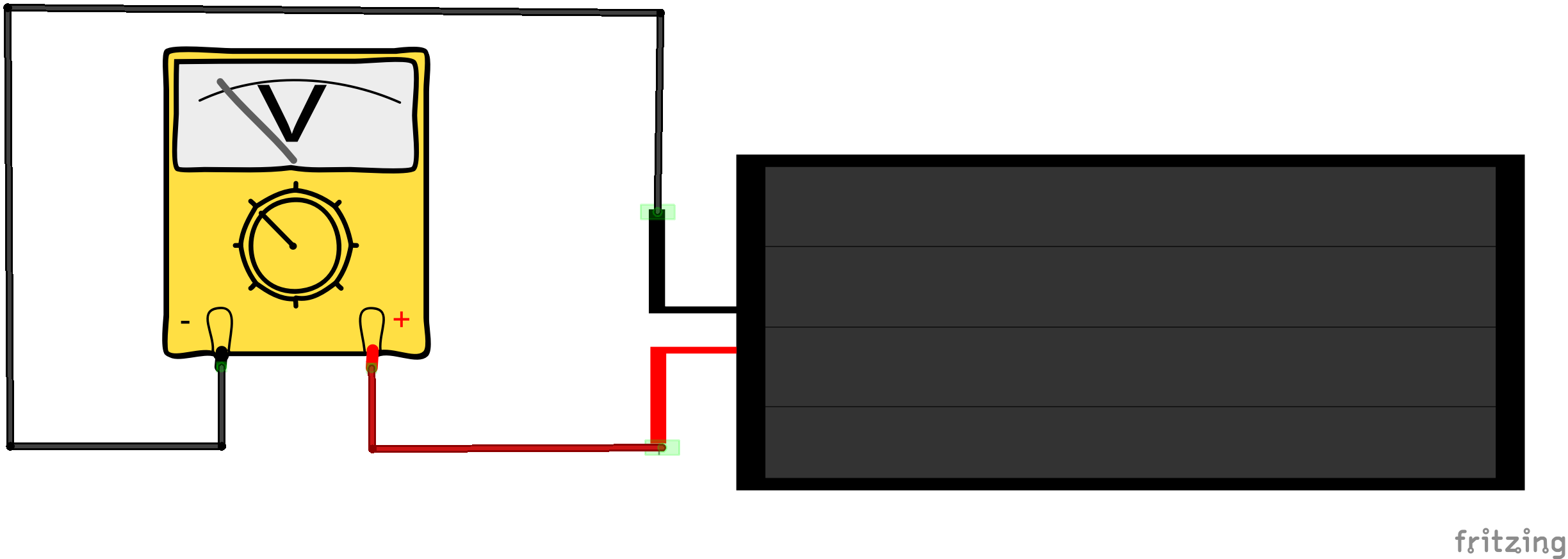
Measure the voltage output for various light levels indoors and outdoors if possible (alternatively close to a bright window). How does the voltage vary? What you are measuring is a close approximation to the Open Circuit voltage of the solar panel, since a multimeter on a Volts setting provides a very high input resistance.
Now set the multimeter to measure Amps, using a range of a least 200 miliAmps. For this example you can leave the leads connected as before. This is one of the very rare occasions when measuring current (Amps) that you can connect a multimeter across (that is in parallel with) a power source. When measuring current the multimeter presents a very low resistance and most power sources will therefore output a high current that will usually damage the multimeter. However, solar panels are not conventional power sources and small panels will only output currents in the milliAmp range. As before measure the current for various light levels indoors and outdoors. What you are measuring is a close approximation to the Short Circuit current of the solar panel.
Use the maximum voltage and current measured to estimate power output of the solar panel. Does this agree with the specification of the panel. If not, why could this be?
In this lab we will use the Arduino MRK WAN 1310 LoRa board from the previous workshop, as LoRa is designed for low power operations.
We are going to use the LoRa sensor example from the previous lab. Wire up the circuit you used in the last lab and load the sketch onto the Artduino LoRa board. Check the sketch is working correctly.
Now disconnect the USB cable you used to power the board.
To measure the current drawn by your Arduino LoRa board you will find it convenient to power the board via a benchtop power suppy (PSU). Ensure the voltage output of the bench power supply is set to 5.00 V. Connect the positive output of the PSU to the Vin pin of the Arduino LoRa board and the negative output of the PSU to the GND pin of the Arduino LoRa board (as shown in the diagram below). Before you switch on the circuit ask a tutor to check you have set up the PSU correctly.
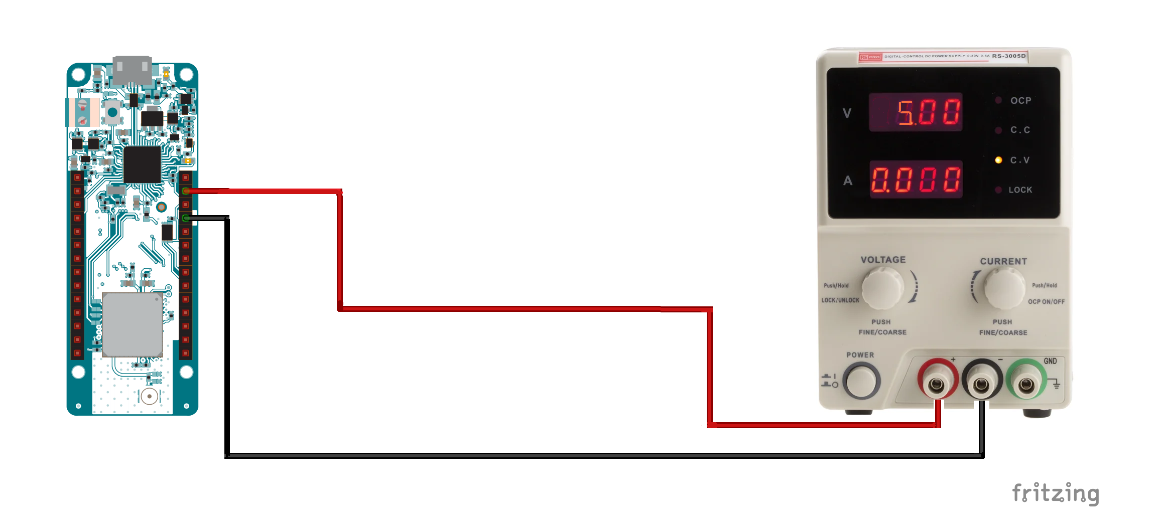
After switching on the PSU you should be able to read the current consumption directly off the PSU current display. You may find the current varies particularly when the LoRa radio is transmitting. Record the maximum current drawn and also estimate the average current consumption.
UseP = V x I to estimate the average and peak power consumption, assuming a 5V power supply.
How does the power output from the solar panel compare with the power consumption of the LoRa board?
As you will have noticed, the power output from small solar panels is limited under most lighting conditions and is particularly poor indoors. The specification for solar panels usually quote power figures obtained under an irradiance of 1000 W/m2, equivalent to cloudless conditions at the Equator! In the UK the maximum outdoor solar irradiance does not exceed 800 W/m2 and the average annual value is about 100 W/m2. Consequently if we wish to solar power a project, we usually need to pay attention to minimising power consumption. A major drain on power is wireless data transmission and we chose LoRa for this example because it is designed to minimise power consumption, while still enabling the upload of data to remote services.
One way to reduce power consumption further is to increase the delay between data uploads, thereby reducing the average time the radio is transmitting compared to being idle. However, we can usually reduce the power budget further by using a suitable Low Power library.
Upload the following sketch to your board. You will need to change the AppEUI and AppKey as appropriate.
#include <MKRWAN.h>
#include <ArduinoLowPower.h>

// First install "DHT sensor library" via the Library Manager
#include <DHT.h>

// Set your AppEUI and AppKey
const char *appEui = "0000000000000000";
const char *appKey = "<YOUR-APP_KEY>";

#define debugSerial Serial
#define DHTPIN 2  //Digital Pin 2
#define DHTTYPE DHT22

DHT dht(DHTPIN, DHTTYPE);


LoRaModem modem;


void setup() {

  debugSerial.begin(9600);

  // Wait a maximum of 10s for Serial Monitor
  while (!debugSerial && millis() < 10000)
    ;

  //Initialise the DHT sensor
  dht.begin();

  // change this to your regional band (eg. US915, AS923, ...)
  if (!modem.begin(EU868)) {
    Serial.println("Failed to start module");
  }

  Serial.print("Your device EUI is: ");
  Serial.println(modem.deviceEUI());

  int connected = modem.joinOTAA(appEui, appKey);
  if (!connected) {
    Serial.println("Something went wrong; are you indoor? Move near a window and retry");
  }

}


void loop() {

  debugSerial.println("-- LOOP");

  uint16_t humidity = 100*dht.readHumidity(false);

  // false: Celsius (default)
  // true: Farenheit
  uint16_t temperature = 100*dht.readTemperature(false);

  debugSerial.print("Temperature: ");
  debugSerial.println(temperature);
  debugSerial.print("Humidity: ");
  debugSerial.println(humidity);

  byte payload[4];
  payload[0] = highByte(temperature);
  payload[1] = lowByte(temperature);
  payload[2] = highByte(humidity);
  payload[3] = lowByte(humidity);

  modem.beginPacket();
  modem.write(payload, sizeof(payload));
  int err = modem.endPacket(true);
  if (err > 0) {
    Serial.println("Message sent correctly!");
  } else {
    Serial.println("Error sending message");
  }

   LowPower.deepSleep(60000);
}
You will need to use the Arduino IDE Library Manager to install the Arduino Low Power library. Run the sketch and measure the current drawn by the board as before, and record the peak current and estimate the long term average current.
You should find the average current drawn by the board is much lower now.
A solar panel on its own is usually not sufficient to power a project (what happens at night?). So normally we will use a battery to power the project, with the solar panel being used to maintain the battery charge. Lithium Polymer (LiPo) batteries are a common choice for solar powered projects as they have a very high energy density, allowing compact and lightweight installations. However, LiPo batteries in particular need a specialist charging circuit. In this example we will use the Adafruit Solar LiPo Charger board. Connect up your LoRa board, battery and solar panel guided by the schematic shown below.
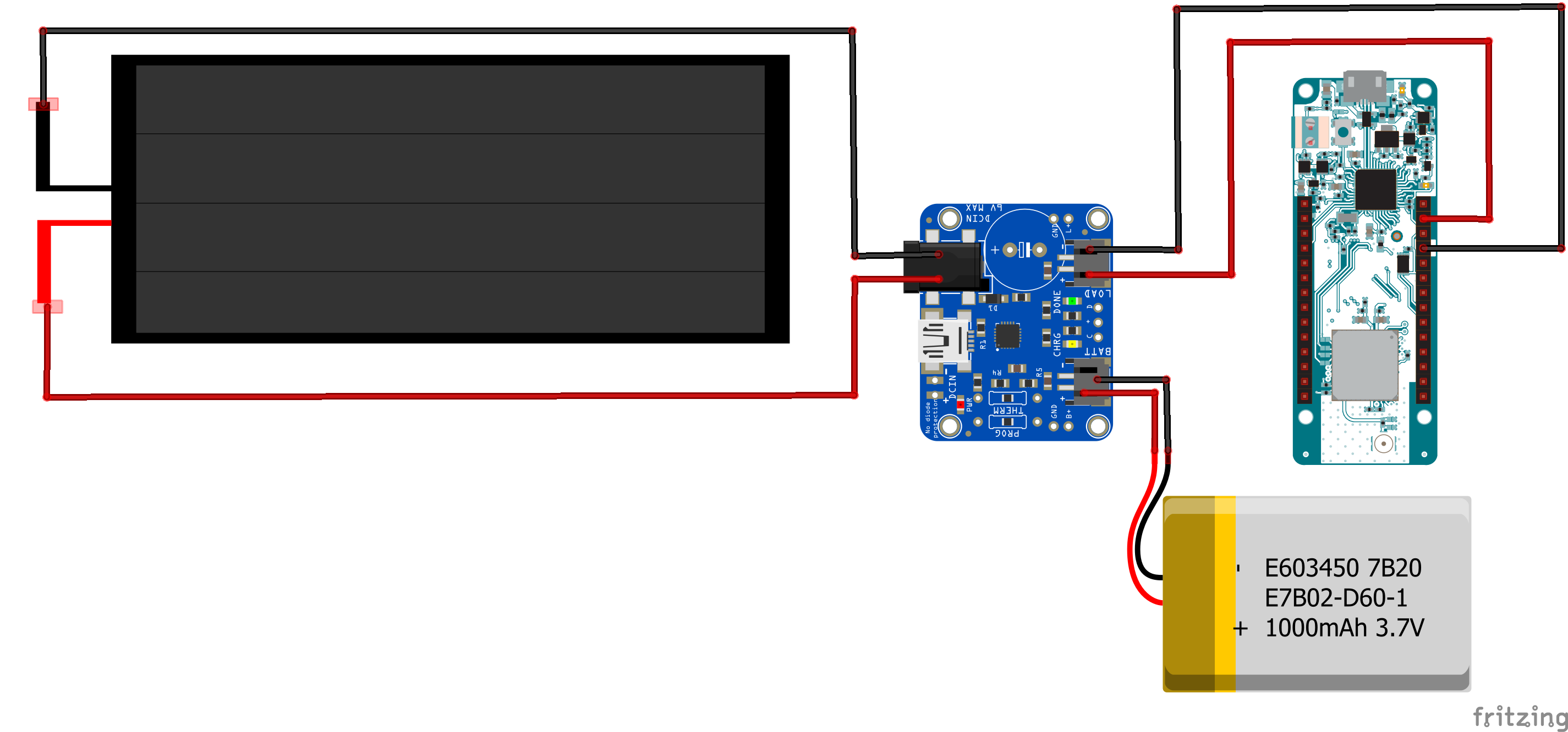
Plug the jack plug from the solar panel into the jack socket on the solar charger board. Plug the JST connector from the battery into the BATT socket on the solar charger board. Using the JST terminated leads, plug the JST connector into the LOAD socket on the solar charger board and use the unterminated end of the leads to power the LoRa board via its Vin pin (red lead) and GND pin (black lead). Keep your sensors connected to the board as before. Check the board is operating correctly and transmitting your sensor data to the Things Network.
You final task is to measure the voltage and current produced by the solar panel when driving a real circuit. These values may be different from the open circuit voltage and short circuit current you measured previously. To measure the current output by the solar panel you will find it useful to use the male and female jack plug adapters. Use these values to calculate the power output of the solar panel. Will this be sufficient to power the project indefinitely? If not how could you rectify this?