- Breadboard
- Arduino UNO
- USB A to B cable
- Servo
- LM335 Temperature Sensor
- 1 kOhm resistor
- Ultrasonic Range Finder (HC-SR04)
- PIR sensor
- NeoPixel LED Stick
- M-M jumper wires
- M-F jumper wires
- Cocktail stick
- White paper card
- Double-sided sticky tape/Blue Tac
What You'll Learn
- Using servos
- Using heat sensors
- Using an Ultrasonic range finder
- Using LED strips
- Visualizing range with LEDs
- Stretch task: Using a PIR sensor
Wire up the following simple circuit featuring a servo.
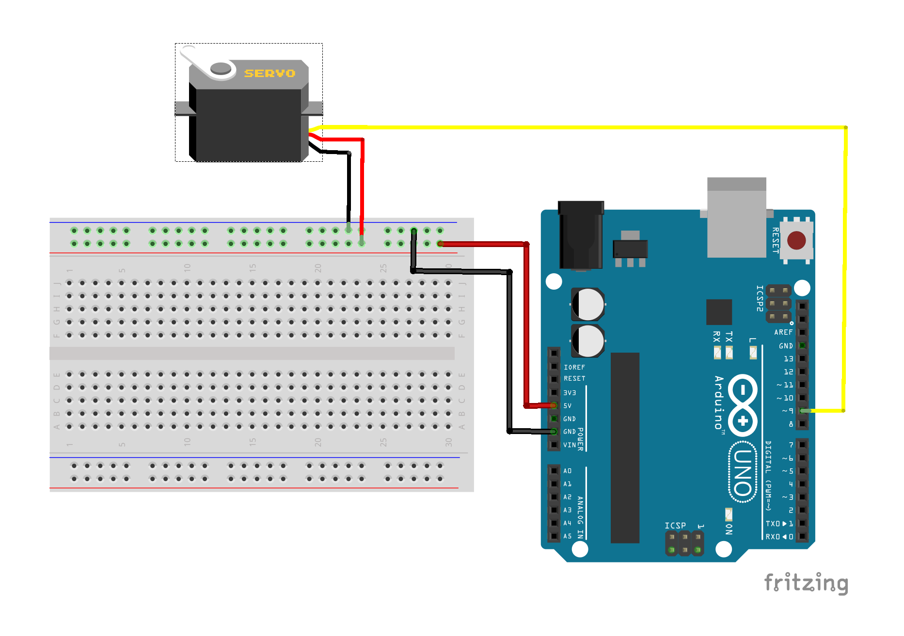
Upload the following basic servo sketch to your Arduino, which sweeps the servo through it full range (0 degrees to +180 degrees) and back again.
/* Sweep
 by BARRAGAN <http://barraganstudio.com>
 This example code is in the public domain.

 modified 8 Nov 2013
 by Scott Fitzgerald
 http://www.arduino.cc/en/Tutorial/Sweep
*/

#include <Servo.h>

Servo myservo;  // create servo object to control a servo

void setup() {
  myservo.attach(9);  // attaches the servo on pin 9 to the servo object
}

void loop() {
  for (int pos = 0; pos <= 180; pos++) { // goes from 0 degrees to 180 degrees
    // in steps of 1 degree
    myservo.write(pos);              // tell servo to go to position in variable 'pos'
    delay(15);                       // waits 15ms for the servo to reach the position
  }
  for (int pos = 180; pos >= 0; pos--) { // goes from 180 degrees to 0 degrees
    myservo.write(pos);              // tell servo to go to position in variable 'pos'
    delay(15);                       // waits 15ms for the servo to reach the position
  }
}
Now add the LM335 temperature sensor to your circuit as shown in the diagram below:
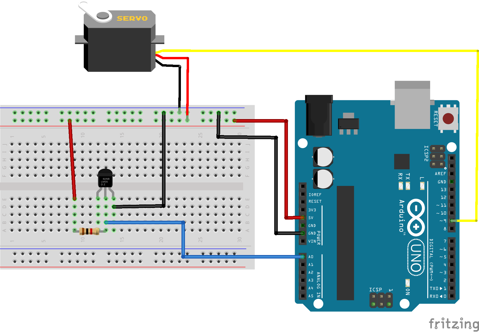
The leftmost pin on the temperature sensor is for calibration and is not used here. The remaining two pins act as a Zener diode whose breakdown voltage is proportional to the temperature. We can measure the voltage across the Zener diode using the analog A0 pin as follows:
float tempVolts = 5.0*analogRead(tempPin)/1024;
The 1 kOhm resitor is used to limit the current through the sensor. The default calibration for this temperature sensor is:
voltage = C X temperature in Kelvin
where C = 10 mV/Kelvin
so we can use the following code to get the temperature in degrees Celsius
  float tempKelvin = tempVolts/0.01;
  float tempCelsius = tempKelvin - 273;
Your task is to modify the sketch (or create a new sketch) to make a simple temperature dial, showing the temperature in degrees Celsius on a scale of 0 to 100 Celsius. You can use the cocktail stick as a pointer, and the white card to make a scale.
You will find the following code snippet useful:
int angle = map(round(tempCelsius), 0, 100, 0, 180);
The round() function takes a floating point number (a decimal number) and rounds it up or down to the nearest integer value.
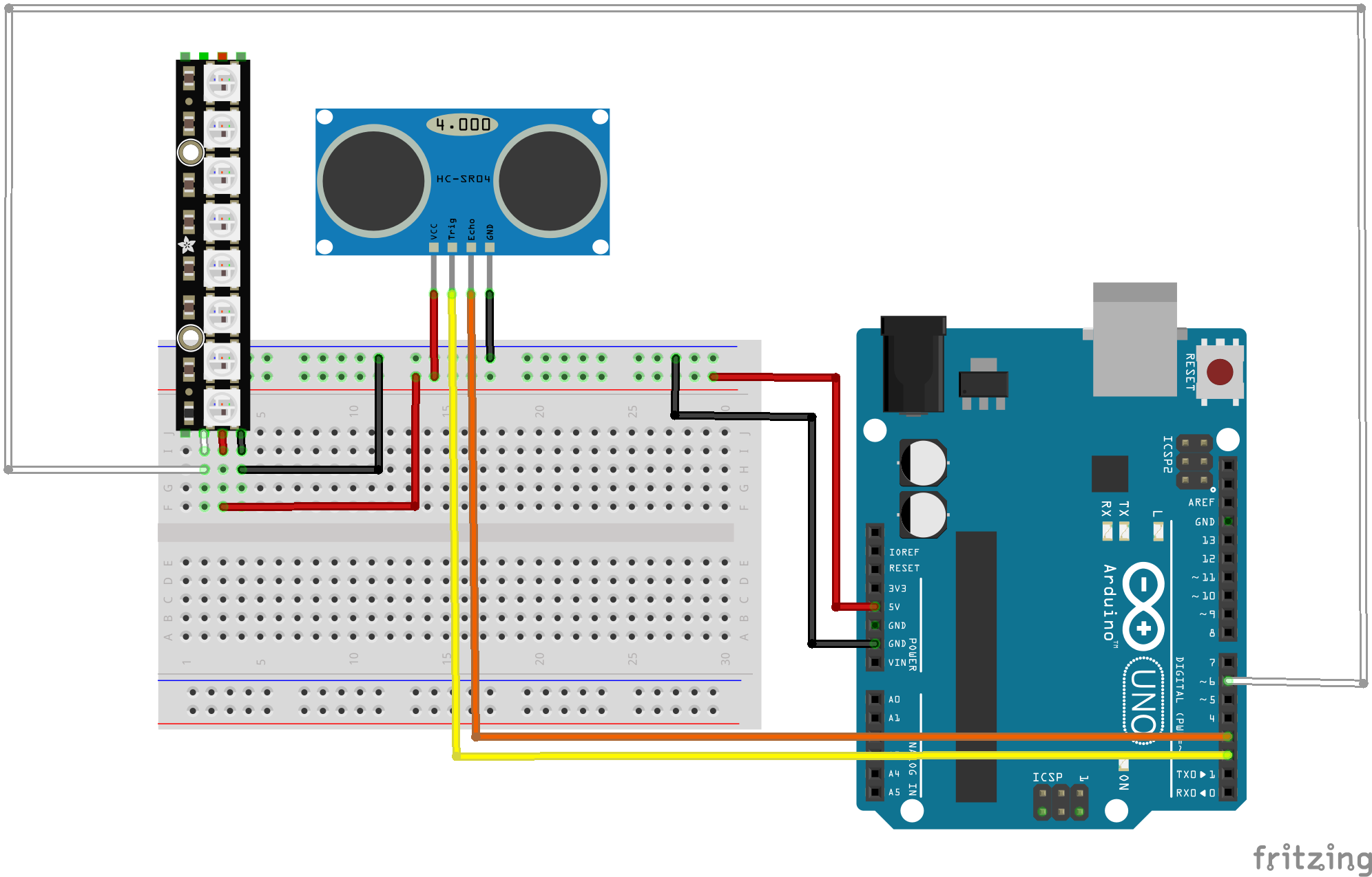
We have seen how to make things move using a servo, now we will look at one way of tracking moving objects, using an Ultrasonic rangefinder.
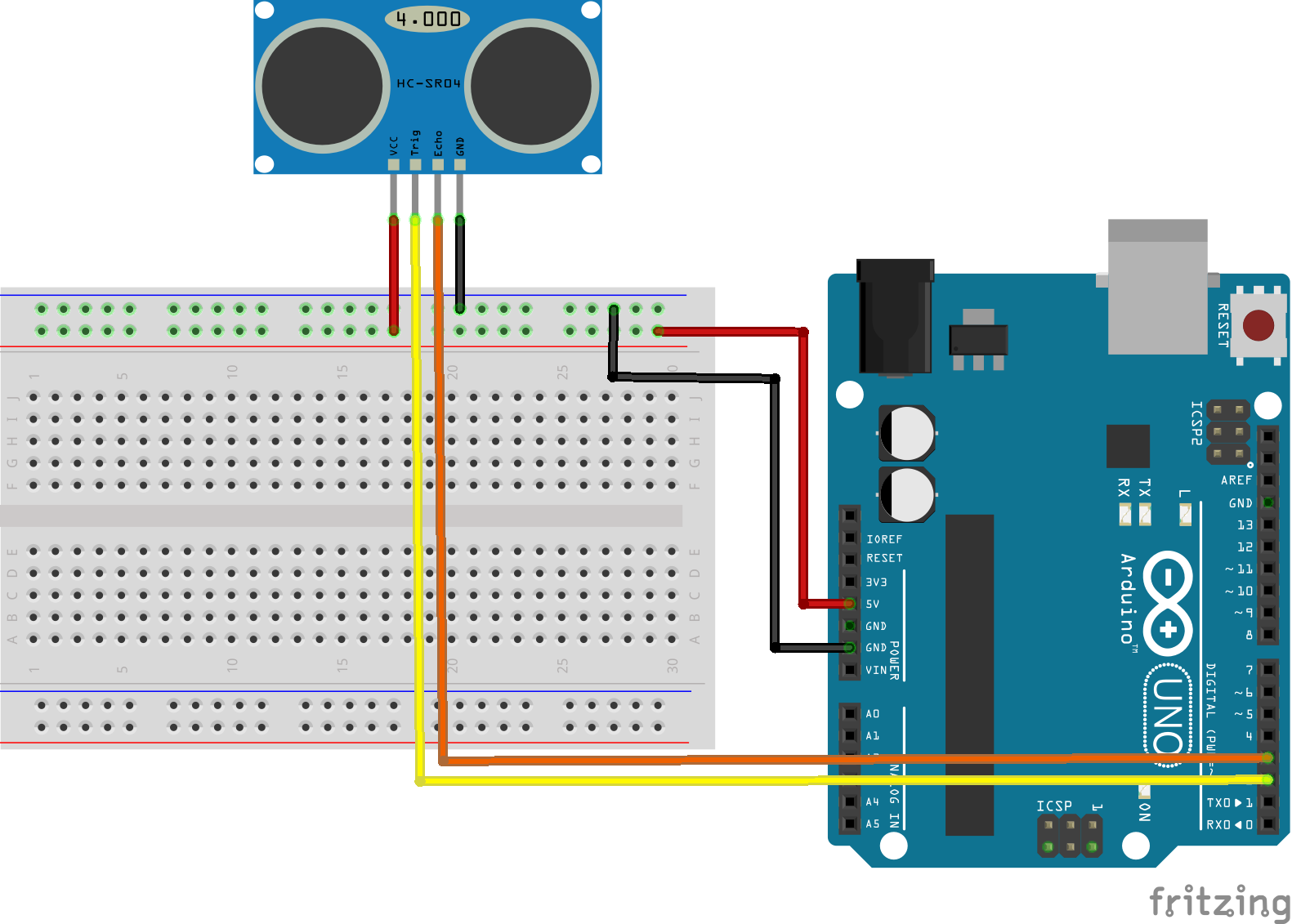
Ultrasonic range finders work in a similar fashion to radar: they send out a high frequency sound pulse, and measure the time taken to receive the echo. The model we are using here is a 4 pin device, which has a Trigger pin to send out the pulse, and an Echo pin which monitors the reflected pulse (as well as Vcc and Ground pins). Some alternative models are 3 pin devices, combining the trigger and echo pins, but otherwise work in the same way.
Wire up a circuit as shown in the diagram below.
Now upload the following sketch to the Arduino
/*
 *  Based on:
 *  https://howtomechatronics.com/tutorials/arduino/ultrasonic-sensor-hc-sr04/
 *
 */

#define trigPin 2
#define echoPin 3

void setup() {
  Serial.begin(9600);
  pinMode(trigPin, OUTPUT); // Sets the trigPin as an Output
  pinMode(echoPin, INPUT); // Sets the echoPin as an Input
}

void loop() {
  // Clears the trigPin
  digitalWrite(trigPin, LOW);
  delayMicroseconds(2);

  // Sets the trigPin on HIGH state for 10 micro seconds
  digitalWrite(trigPin, HIGH);
  delayMicroseconds(10);
  digitalWrite(trigPin, LOW);

  // Reads the echoPin, returns the sound wave travel time in microseconds
  long duration = pulseIn(echoPin, HIGH);
  float distance = 34400*duration/2000000;

  Serial.print("Distance in cm: ");
  Serial.println(distance);

  delay(2000);
}
To generate the outgoing pulse, it is necessary to make the Trigger pin high for 10 microseconds. The rangefinder measures the time taken for the reflected pulse to be received, and represents this by raising the Echo pin high for a corresponding duration. The pulseIn(echoPin, HIGH) function measures the duration of the high pulse on the Echo pin. Remember that the time taken to receive the echo, corresponds to the time taken for the trigger pulse to travel out to the object and back again. So the distance to the object is determined by half the duration measured in seconds, divided by the speed of sound (34400 cm/s).
Run the sketch with the Serial Terminal open and try placing various objects in front of the rangefinder. Do the results make sense?
We've have seen previously how to drive individual LEDs. However, LED strips and arrays can provide far more impressive displays. Modern LED strips and arrays are frequently made of individually addressable, RGB (Red, Green,
Blue) LEDs. LEDs strips are typically driven via 3 pins: Vcc, Gnd and a control (data) pin. Driving individually addressable LEDs via one control wire is not trivial, so here we will use the Neopixel library to abstract away the complexity.
First wire up the LED stick as shown in the diagram below.
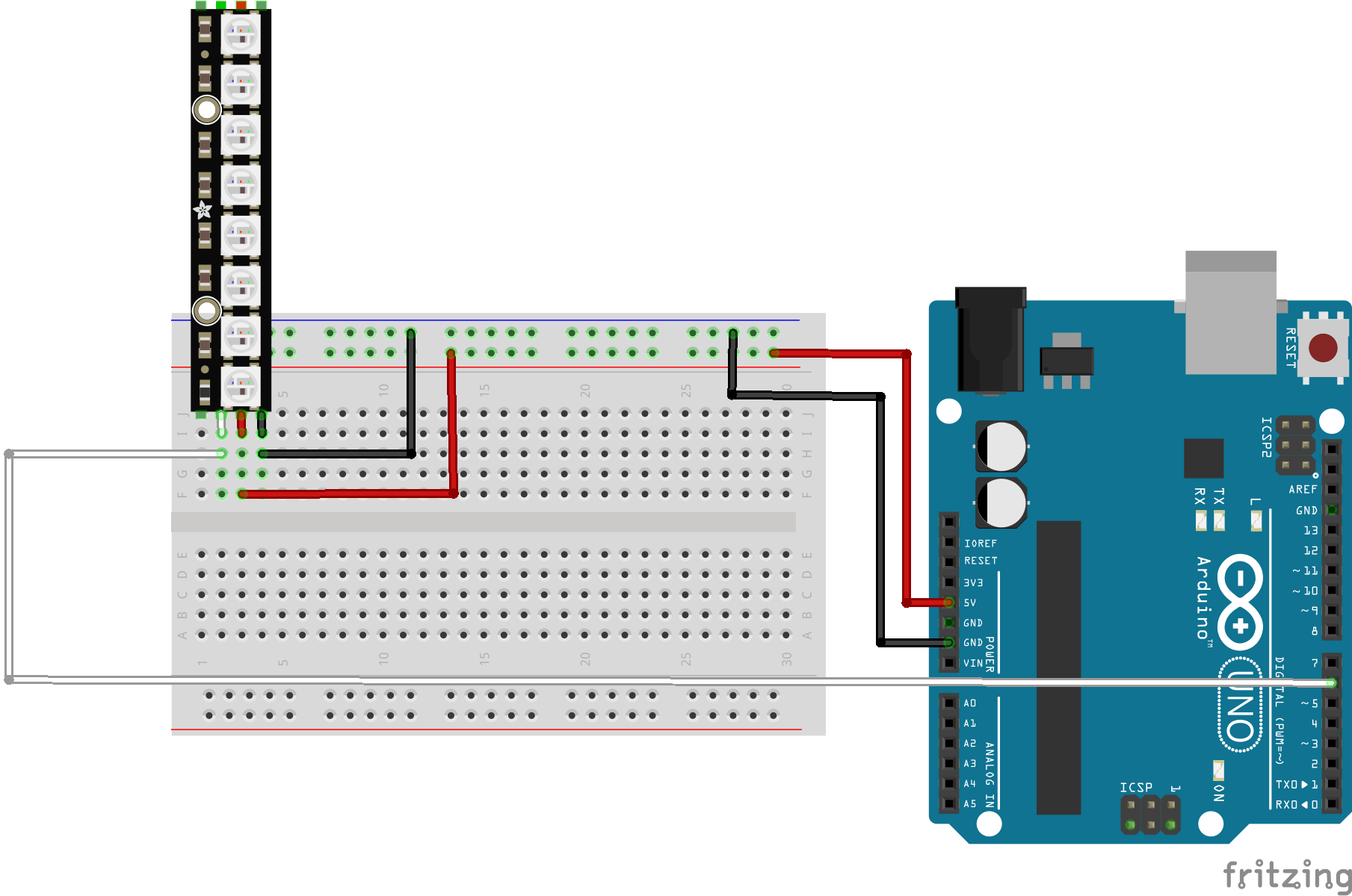
We can drive this small LED stick using the Arduino 5V output, however for large LED strips and arrays you will need to use a seperate power supply.
Use the Library Manager in the Arduino IDE to install the Adafruit Neopixel library. Then upload the following example sketch.
#include <Adafruit_NeoPixel.h>

#define PIN 6
#define NUMPIXELS 8
#define DELAYVAL 500

Adafruit_NeoPixel pixels(NUMPIXELS, PIN);

void setup() {
  pixels.begin();
}

void loop() {
  pixels.clear();
  for(int i=0; i<NUMPIXELS; i++) {
    pixels.setPixelColor(i, 150, 0, 0);
    pixels.show();
    delay(DELAYVAL);
  }
}
The colour of individual LEDs is set via the setPixelColor() function, where the first argument is the number of the individual LED, and the next three arguments are the R,G,B values.
Run the sketch and check it is working correctly. Trying changing some of the R,G,B values and observe the effect.
Your final task is to use the LED stick to visualise the output of the ultrasonic range finder. Add the range finder back into your circuit as shown below.
Combine the Range Finder and LED sketches and then modify the sketch to make a proximity detector, in other words map the range so that a close object illuminates all the LEDs and a far away object illuminates none.
For a stretch task you can try swapping out the Ultrasonic rangefinder for a PIR sensor. PIR sensors detect movement (but do not track range) and are the basis for many burglar alarms.
Wire up the circuit as shown in the diagram below
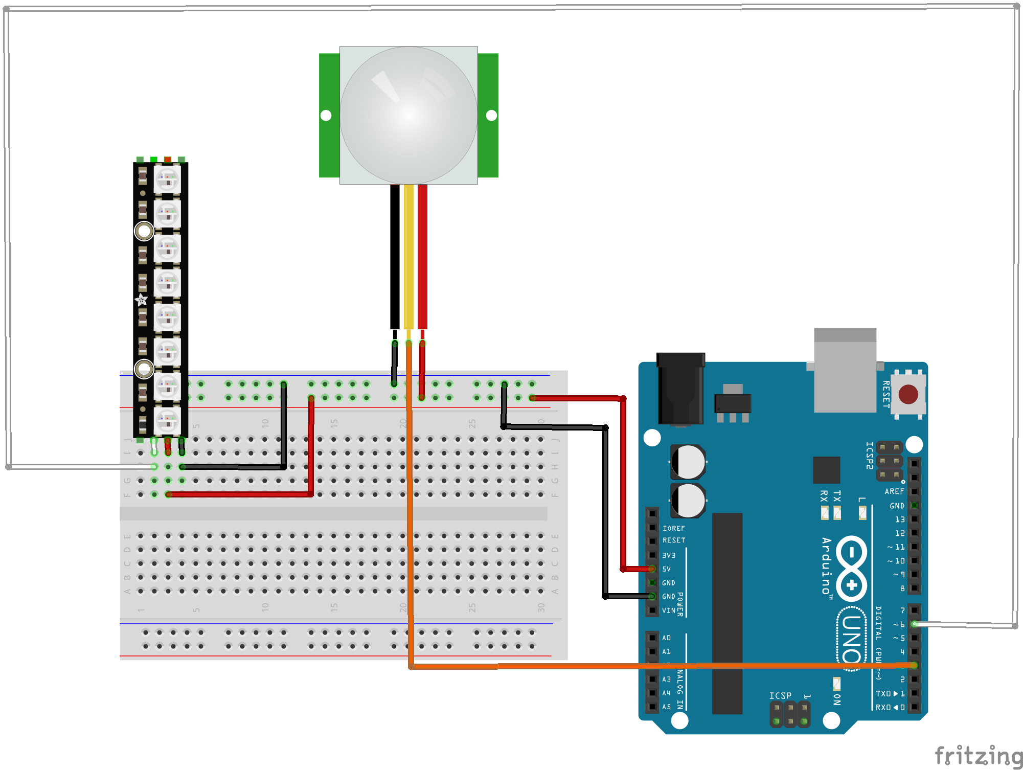
You will find this tutorial useful, but beware the wiring is incorrect for the PIR model we use! You may have to change the jumper position on your PIR sensor to achieve repeatable triggering as explained in the tutorial. Also the PIR sensor needs some time to calibrate, so there should not be any movement in front of the PIR sensor for up to 15 seconds at start up. If you are interested in exploring this device further here is the data sheet for the sensor we use.
You will find the PIR sensor behaves differently to the Ultrasonic rangefinder, so you won't be able to make full use of the LED strip, but see if you can improvise a partial solution (or swap it out for an ordinary LED).