- Breadboard
- Arduino UNO
- USB cable
- Red LED
- Yellow LED
- Green LED
- 3 x 220 Ohm resistor
- 10 kOhm resistor
- 1 kOhm resistor
- Button
- M-M jumper wires
- M-F jumper cables
- 1 microFarad Capacitor
What You'll Learn
- Using digital pins on an Arduino
- Using buttons
- Debouncing buttons
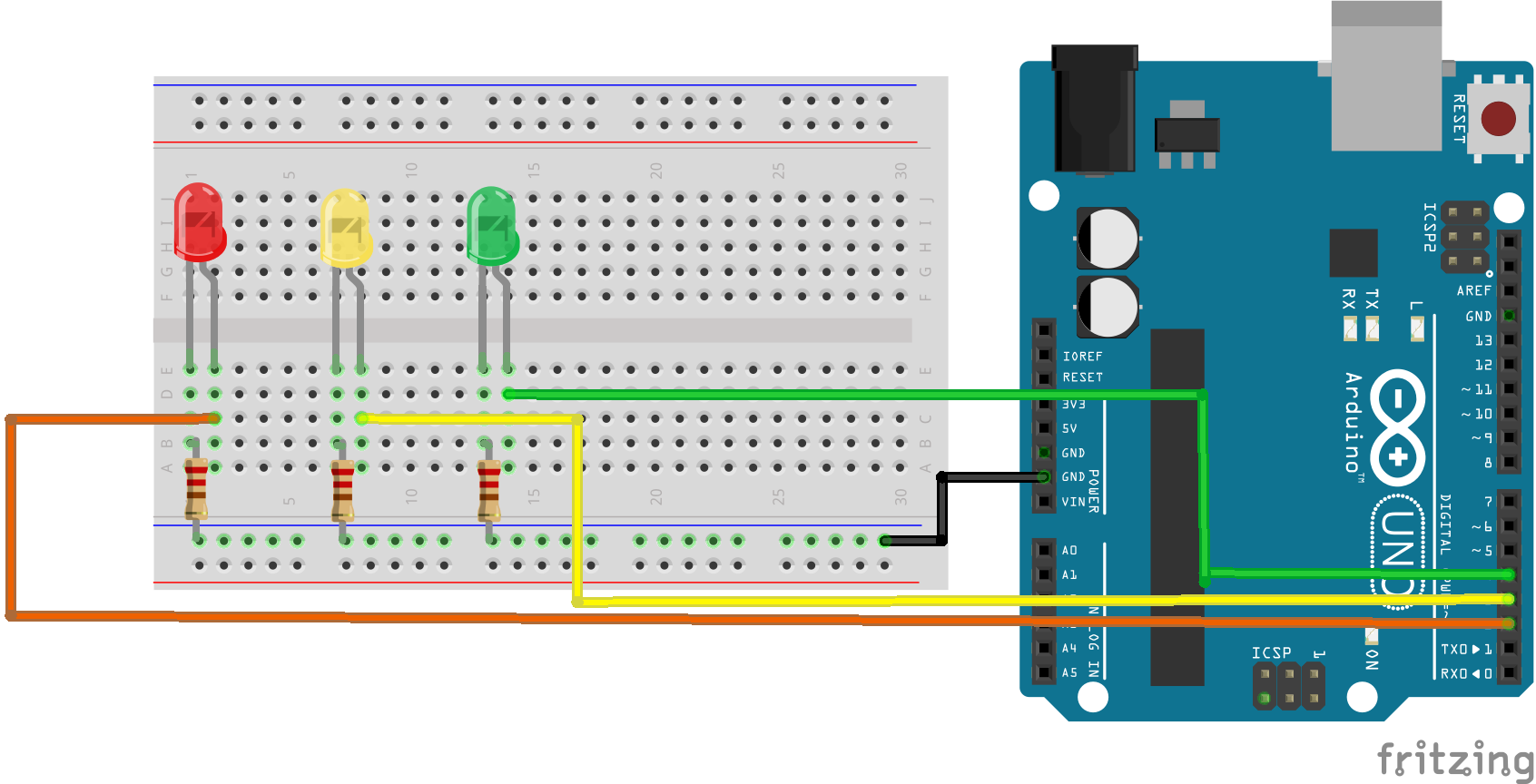
Wire up the following circuit featuring red, yellow and green LEDs driven by digital pins 2, 3 and 4.
Upload the following basic sketch to your Arduino, which blinks the red LED.
#define redLED 2

void setup() {
  // set digital pin 2 to act as an output
   pinMode(redLED, OUTPUT);
}

void loop() {
  digitalWrite(redLED, HIGH);   // turn the LED on (HIGH is the voltage level)
  delay(1000);                  // wait for a second
  digitalWrite(redLED, LOW);    // turn the LED off by making the voltage LOW
  delay(1000);                  // wait for a second
}
Your task is to modify and extend the sketch to make a traffic light. The actual colour sequence of UK and European traffic lights is as follows:
Green
Amber (yellow in this example)
Red
Read and Amber
Green
Choose appropriate timings for the sequence, bearing in mind that you will be asked to demonstrate your traffic light to the lab tutor, so don't make your red or green timings too long!
Now add a button to the circuit as shown below.
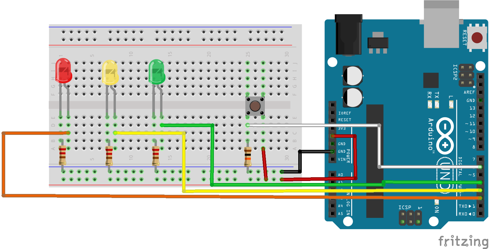
A button is just another form of switch. By default with the switch open (button unpressed), the digital pin 6 is LOW, since it is connected to ground via the 10 kOhm resistor (with the switch open no current flows and therefore no voltage develops across the 10 kOhm resistor).
When the button is pressed, the circuit is closed and digital pin 6 goes HIGH and current will flow through the 10 kOhm resistor to Ground. The 10 kOhm resistor prevents a short circuit between HIGH and Ground and limits the flow of current.
We monitor the state of the button using digital pin 6 as an input.
The operation of the pedestrian crossing should be as follows:
If the traffic light is green when the button is pressed, it should immediately change color to amber, then red as per the normal sequence. If the traffic lights are not green, then pressing the button has no effect.
To help you, here is the skeleton code to drive the green light:
void loop() {
  long lastGreenTime = millis();
  boolean buttonPressed = false;
  while(buttonPressed == false && ( millis() - lastGreenTime < 10000) ){
    //You need to fill in the code here to achieve correct operation of the pedestrian crossing
    //Only two lines are needed
  }
  ...
}
Check your pedestrian crossing is working correctly, then demonstrate it to the tutor.
You may notice that occasionally the Arduino fails to detect a button press. This can occur due to a phenomenon known as bouncing. Bouncing occurs because switches and buttons don't close instantaneously which can resulting in the button state oscillating between LOW and HIGH for a fraction of a second, before fully closing. This can result in the misreading of the state of the button paricularly for fast running loop code that cycles many thousands of times a second.
Bouncing can be tackled in software (i.e. the sketch) or through the use of a capacitor across the button, which acts to smooth out the oscillations. Let's try the latter approach
Your next task is to add a 1 microFarad capacitor across the button as shown in the diagram below.
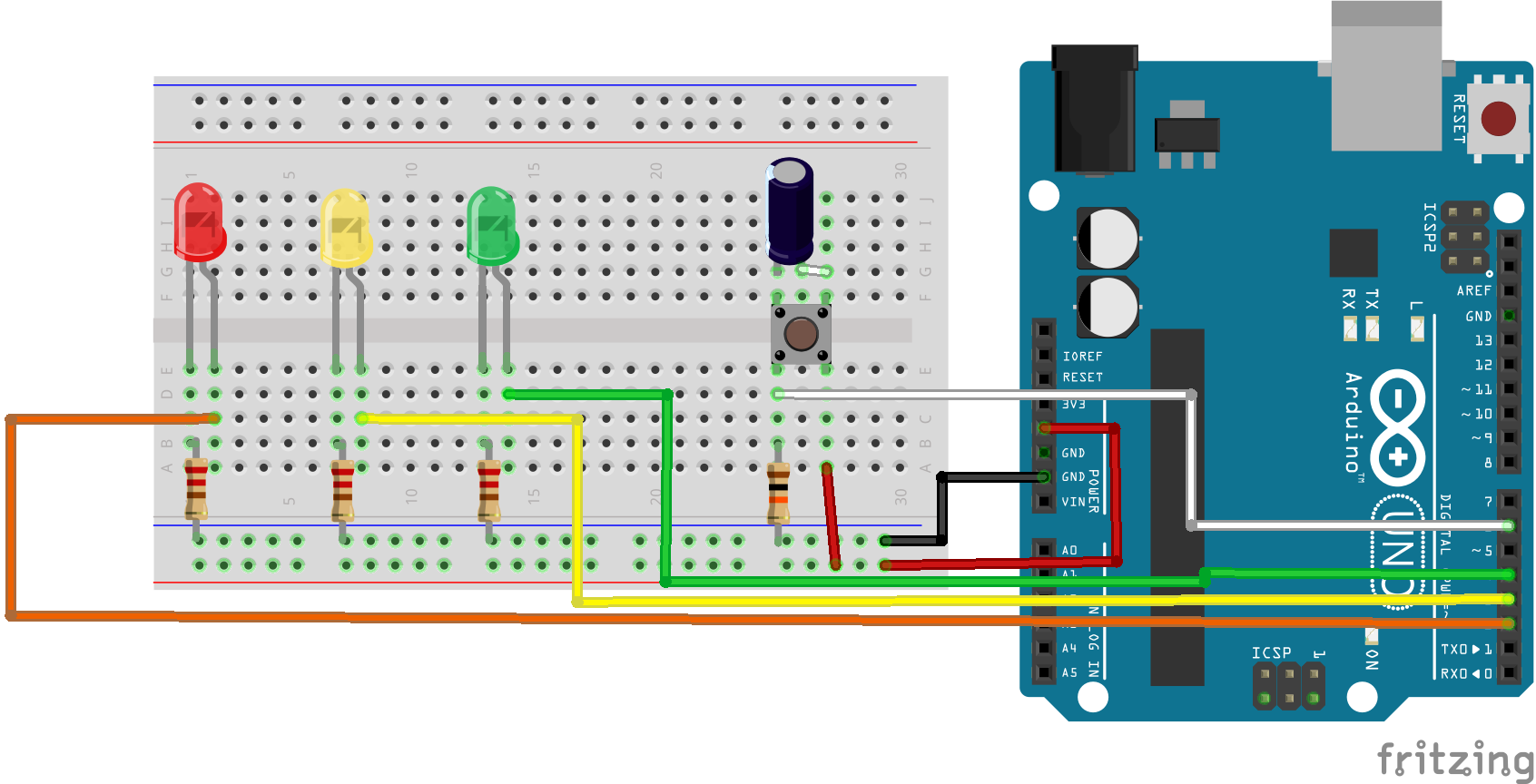
Note the 1 microFarad capacitor used here is an electrolytic capacitor, these are polarised (i.e. have positive and negative terminals) and must be connected the right way around. In this example the positive terminal of the capacitor should be connected to the button terminal that is connected to the Arduino's 5V supply.
Check you sketch is still working correctly. If you were previously noticing issues relating to bouncing, have they been resolved now?