- Breadboard
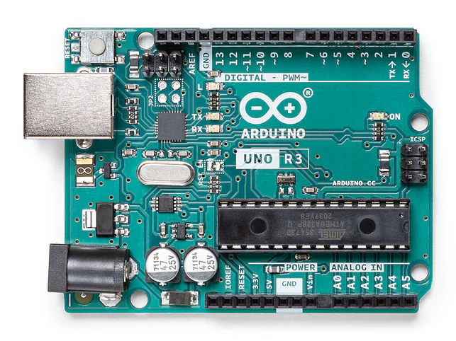
- Arduino UNO
- USB cable
- LDR
- 10 kOhm resistor
- 1 kOhm resistor
- 220 Ohm resistor
- LED
- M-M jumper wires
What You'll Learn
- Introduction to Arduino
- how to measure voltage and current
- Resistors in Series: the Voltage Divider
- Measuring Voltage with the Arduino
- Reading an Analog Sensor
- Driving an Actuator
The Arduino UNO microcontroller is a design classic, originally designed primarily for artists and interaction designers. While not the most powerfull microcontroller by any means, it is simple to use and robust (i.e. student proof). During this course we will be using the Arduino UNO a lot.
If you haven't done so already, you will need to download and install the Arduino Integrated Development Environment (IDE) which is available here. Also you will need to connect your laptop to the Arduino UNO using the USB A to B cable which should be included in your kitbag.
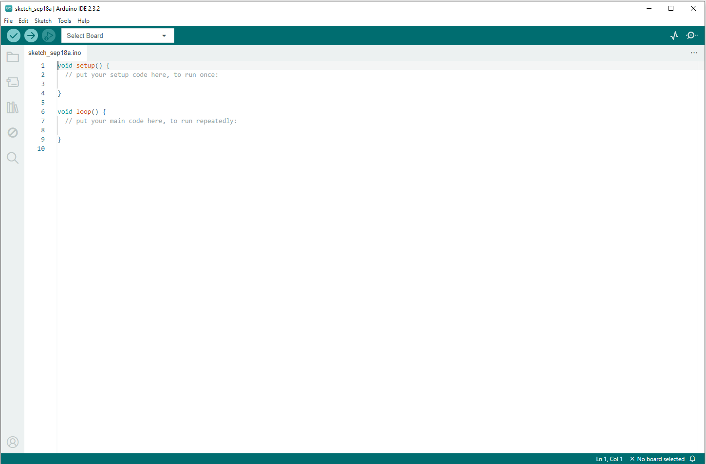
Startup the Arduino IDE. You should see something like this:
You need to tell the IDE what type of board you are using. Use the ‘Select Board' option and select ‘Arduino Uno' as shown below:
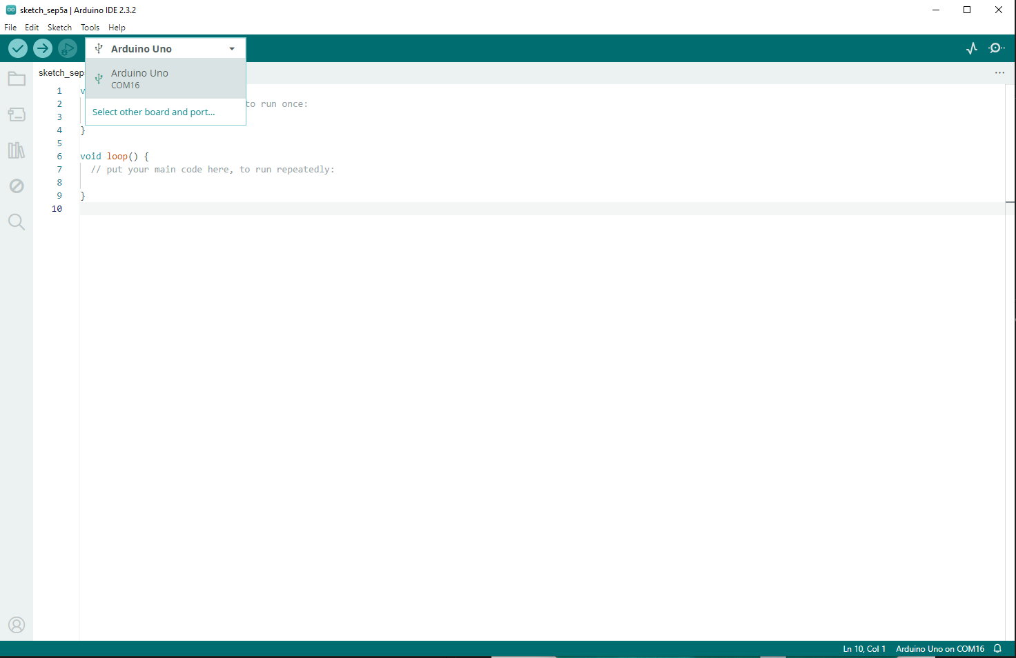
The communication (COM) port maybe different for your installation.
You are now ready to upload a sketch to your Arduino, but before we do that we will try out a few basic measurements.
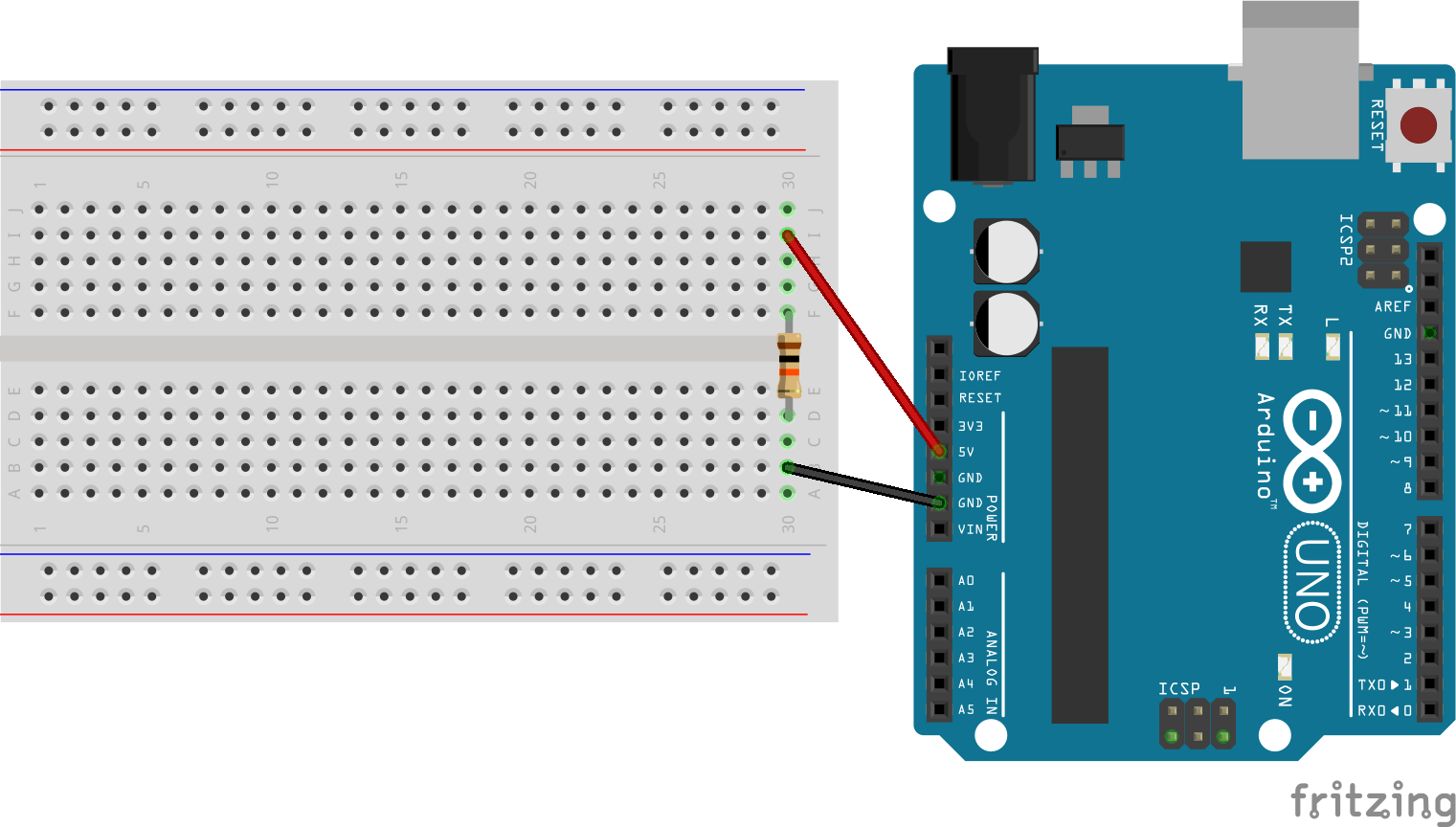
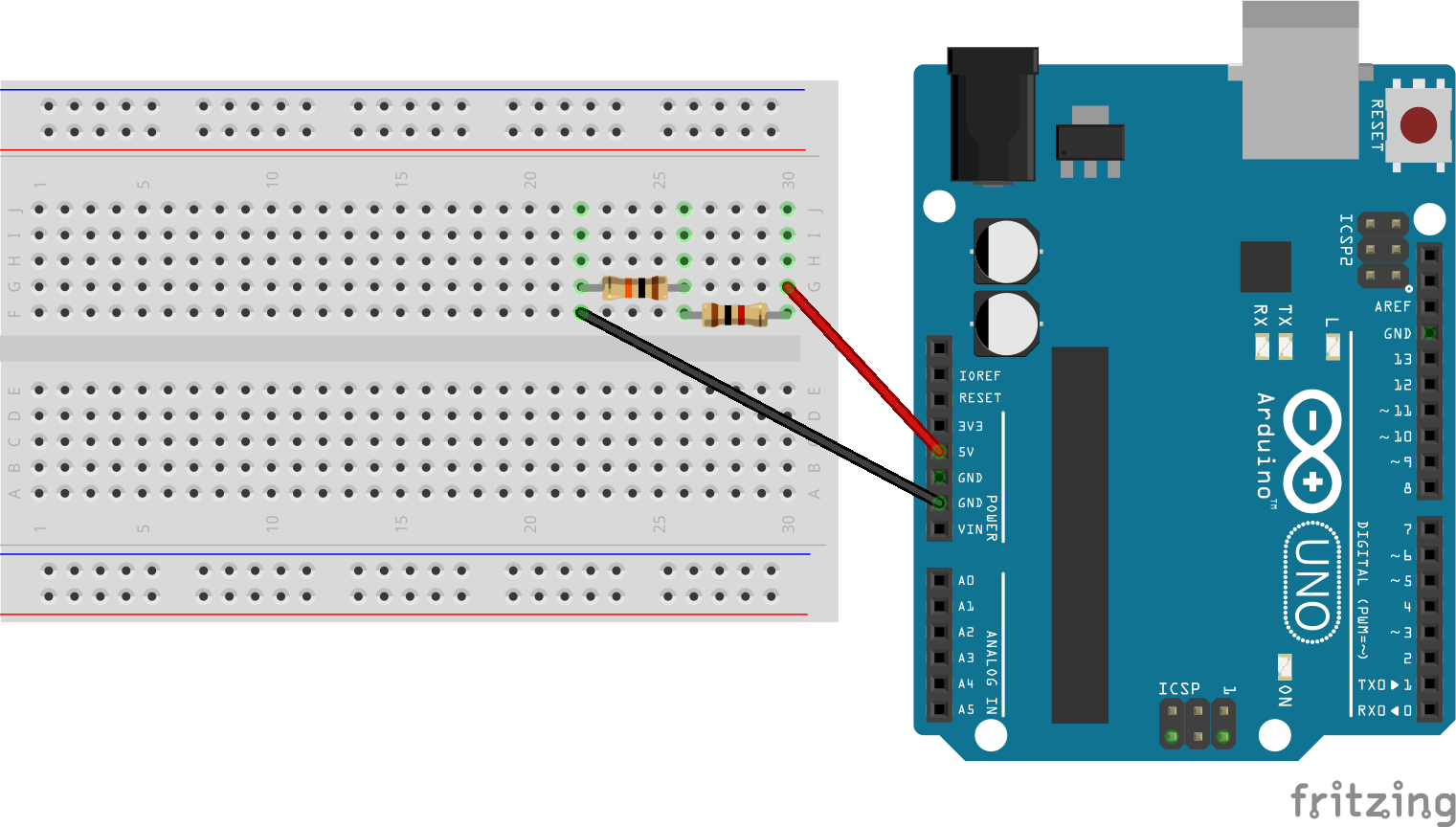
Wire up the following simple circuit featuring a 10, 000 Ohm (that's 10 kOhm) resistor.
Find a multimeter, and set it to a suitable Volt range. What is the voltage across the resistor? Is it what you expected?
Set your multimeter to measure current, that is Amps. Measure the current through the circuit. You may have to refer to the Lecture notes to find out how to do that. What current do you measure? Does this agree with Ohms Law, I = V/R ?
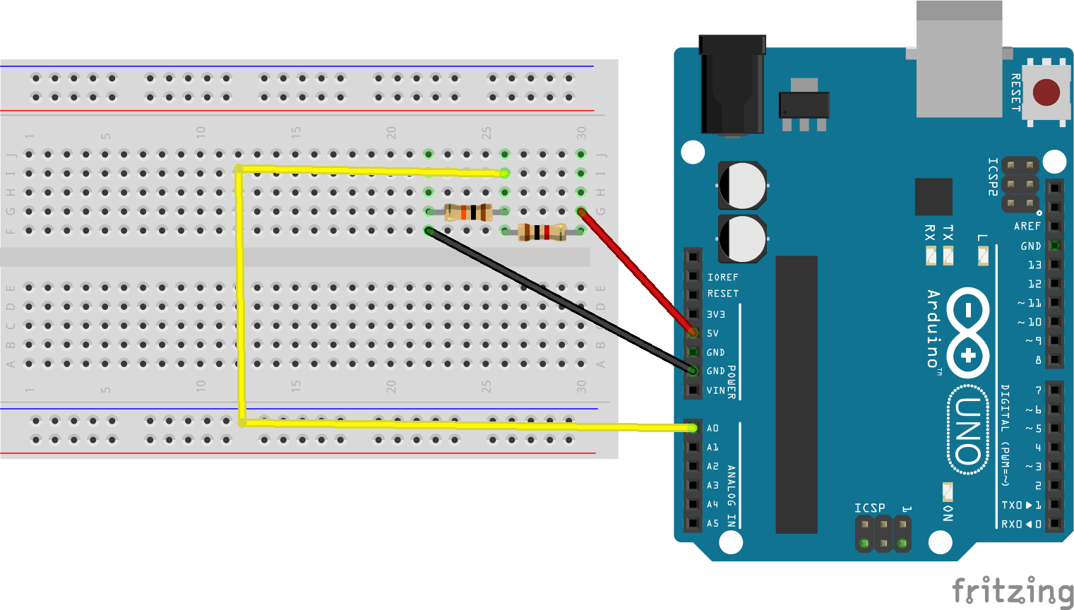
Wire up the following circuit featuring a 10 kOhm resistor and a 1 kOhm resistor in series.
Set the multimeter to a suitable Volt range and measure the voltage across the 10 kOhm resistor and then across the 1 kOhm resistor. Are the results what you would expect?
We will now use the analog inputs of the Arduino to measure voltage. Connect a wire from Analog Pin 0 (A0) on the Arduino to the junction of the 1 kOhm and 10 kOhm resistor as shown below.
As we saw in the lecture, computers including microcontrollers are digital systems. Microcontrollers approximate an analog value using quantisation. By default an Arduino UNO uses a 10 bit analog to digital converter (ADC). This means that it will map input voltages between 0 and the operating voltage (5V for the UNO, but some smaller boards operate at 3.3V) into integer values between 0 and 1023 (as a 10-bit binary number can have 1024 discrete values).
Therefore to convert the output of analogRead() to an actual voltage we use the following relation:
float voltage = Vcc*analogRead()/1024;
The full arduino sketch is shown below:
#define analogPin A0
#define Vcc 5.0 //Board voltage

void setup() {
  // put your setup code here, to run once:
  Serial.begin(9600);
}

void loop() {
  // put your main code here, to run repeatedly:
  float voltage = Vcc*analogRead(analogPin)/1024;
  Serial.print("Voltage is: ");
  Serial.println(voltage);
  delay(5000);
}
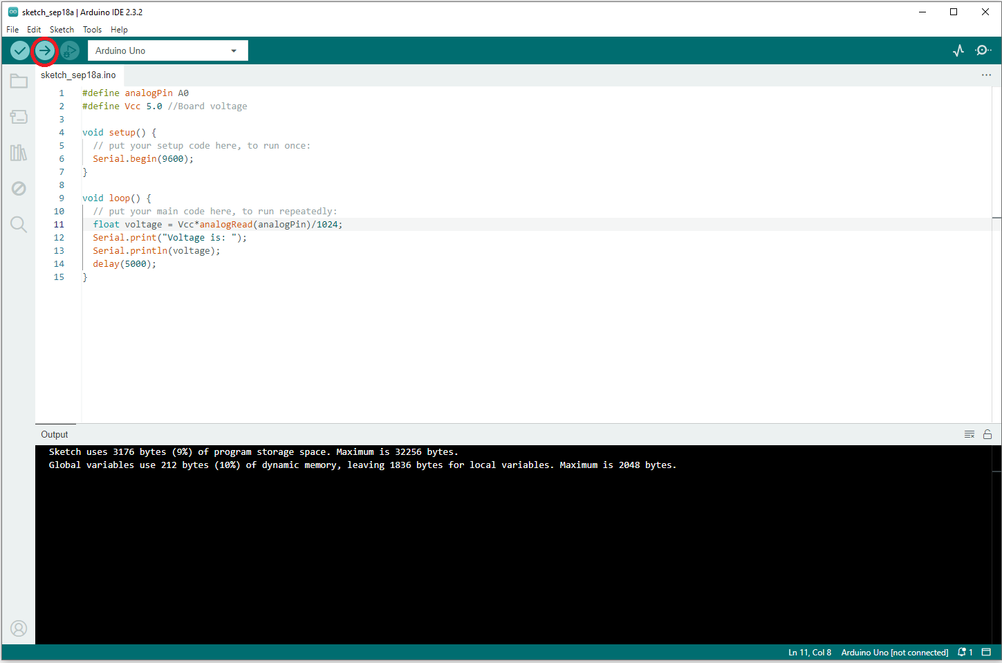
Upload this sketch to the Arduino as shown below
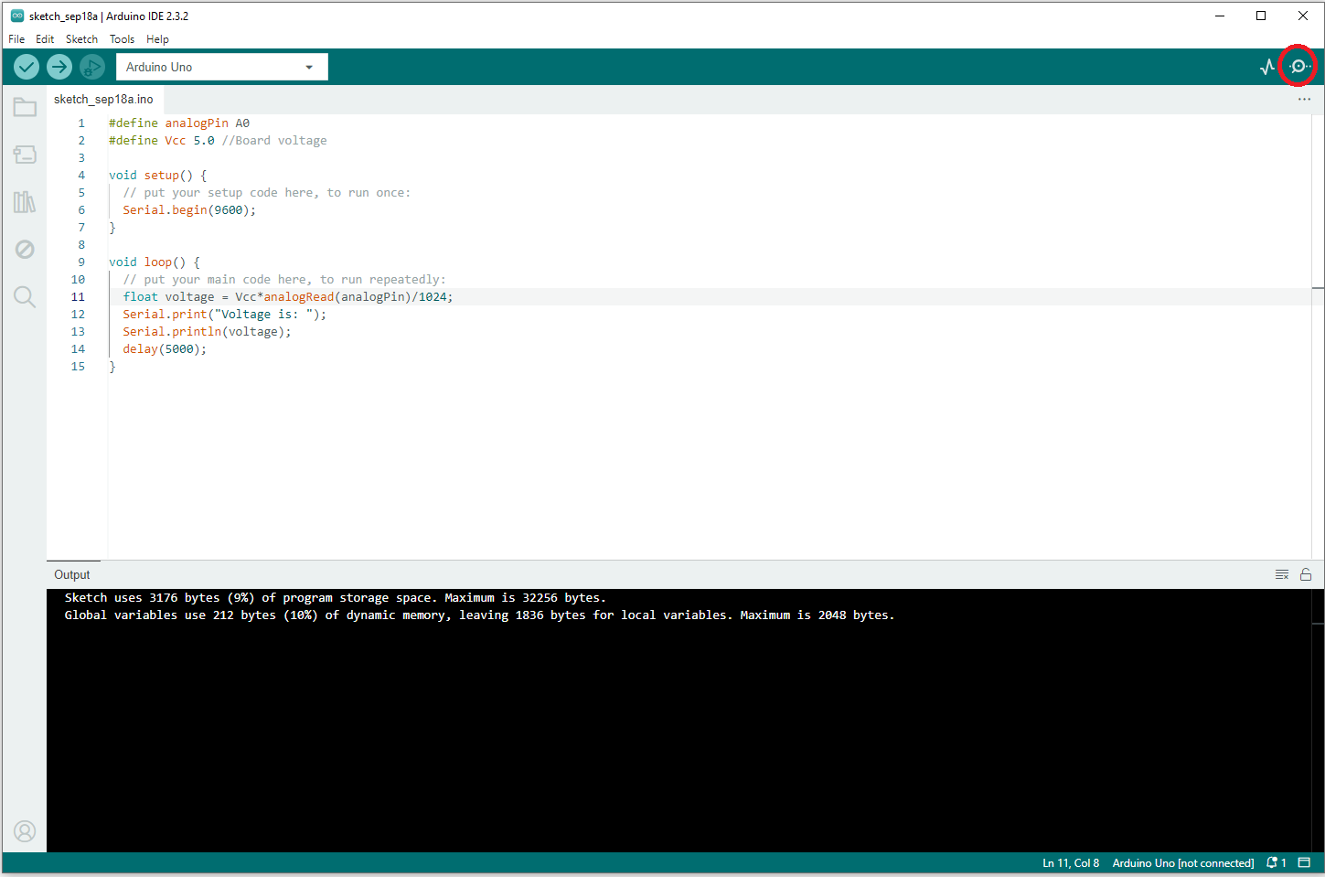
and open the Serial Monitor (see below)
to view the voltage value. Does this agree with the multimeter readings?
We are now going to use analogRead() to read values from a light dependent resistor (LDR). Return to your circuit and replace the 10 kOhm resistor with a light dependent resistor and replace the 1 kOhm resistor with the 10 kOhm resistor as shown in the diagram below.
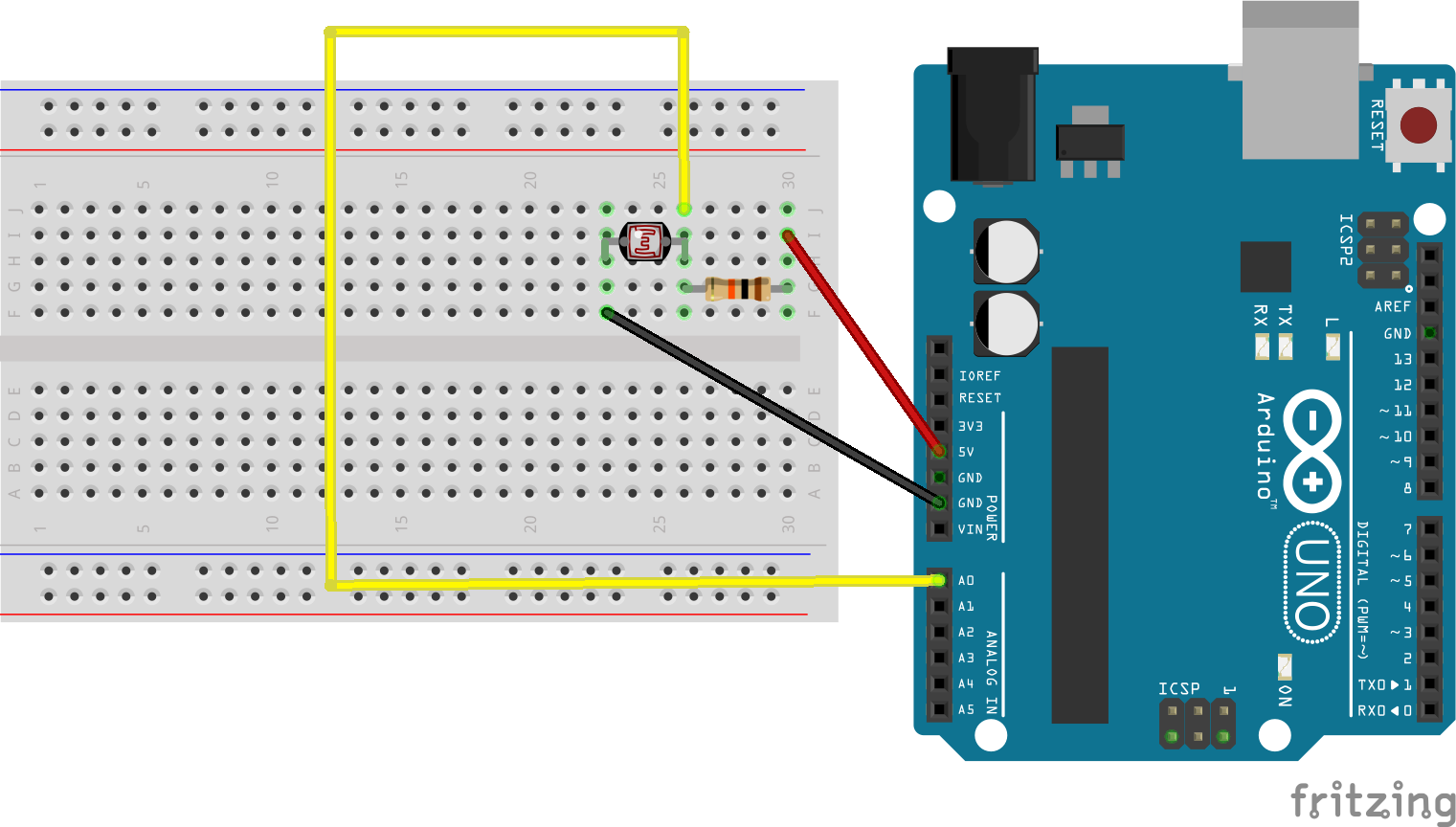
LDRs are semiconductor devices whose resistance decreases as light levels increase. Open the Serial Monitor and check how the voltage varies with different light levels (try covering the LDR with a finger or shining a torch from your smartphone on it).
The circuit you have created is effectively two resistors in series (the LDR in series with a 10 kOhm resistor). How would you calculate the instantaneous resistance of the LDR using Ohm's Law? Modify the sketch to output the instantaneous resistance of the LDR. In the dark, the resistance of the LDR is nearly 1 MOhm (1 million ohms) whereas in light conditions the resistance of the LDR will be nearer 1 kOhm.
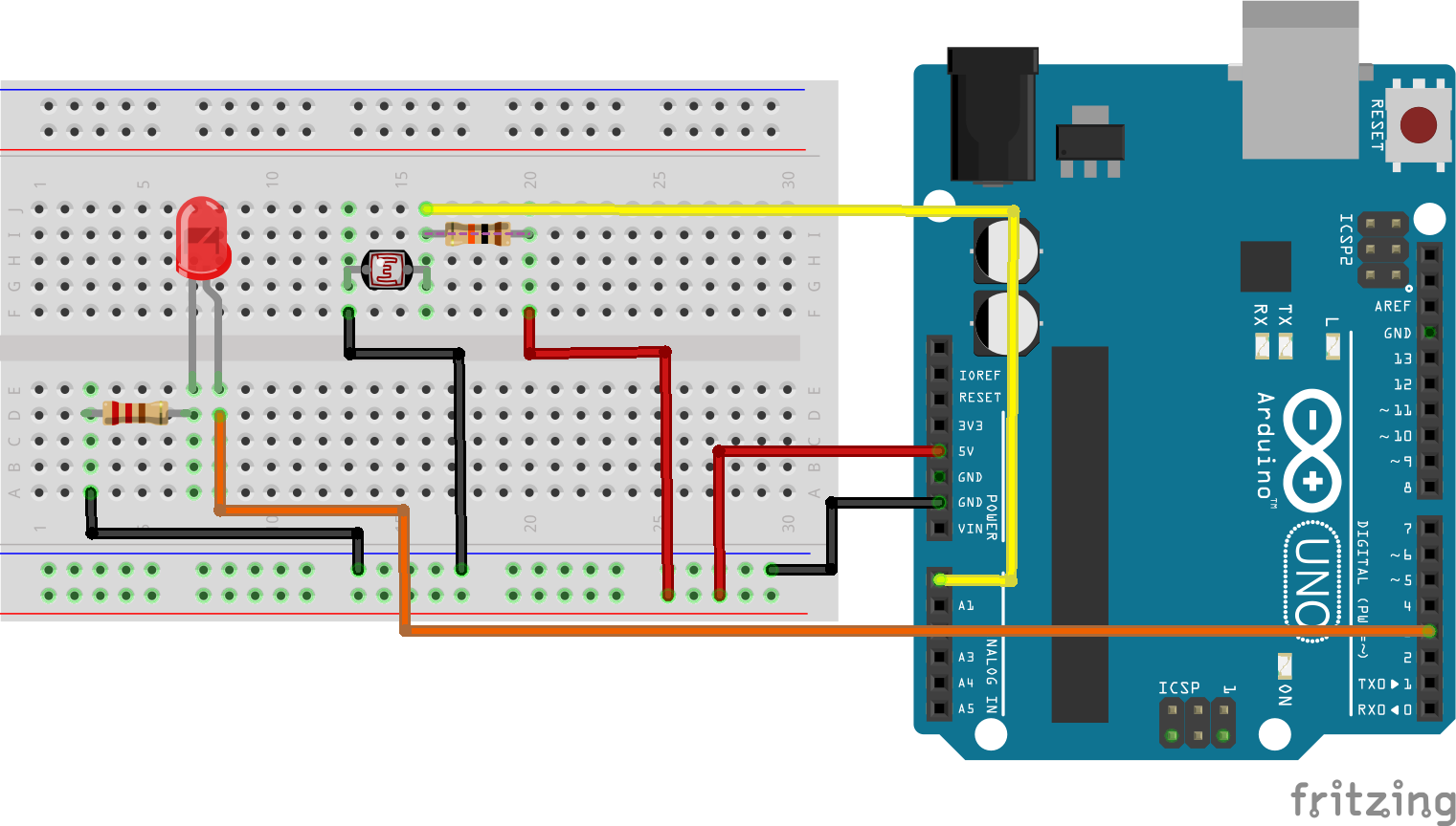
Finally, let's wire up an actuator. In this example we will use a LED to reflect the light levels measured by the LDR using Pulse Width Modulation (PWM).
As this circuit is a bit more complex, the design makes use of the power rails of the breadboard (which is a habit you should get into with your circuits). As well as the LED, an additional 220 Ohm resistor has been added in series with it. This limits the current through the LED and is normal practice. Wire up LED as shown below. The LED is driven by the (digital) Pin 3, which is one of the pins that supports PWM.
In your sketch, immediately below the line #define analogPin A0 add the follwing line:
#define ledPin 3
In the loop() code, below the line Serial.println(voltage); add the following:
  int dutyCycle = 127;
  analogWrite(ledPin, dutyCycle);
The dutyCycle variable can take any value from 0 (always off) to 255 (always on) and determines the brightness of the LED. Experiment with different values for dutyCycle in your sketch. Your final task is to use the output of the LDR to programatically control the brightness of LED.