In this workshop you will learn how to:
- Wire up and write RGB colour values to a neopixel connected to an Arduino MKR1010
- Write RGB colour values to the remote Vespera light installation using MQTT via an Arduino MKR1010
These examples are aimed at helping kickstart ideas on how you can send colour values to Vespera. Working directly with the "BYTE pixel array" will allow you to test out ideas locally on a web page before using the physical Vespera light installation.
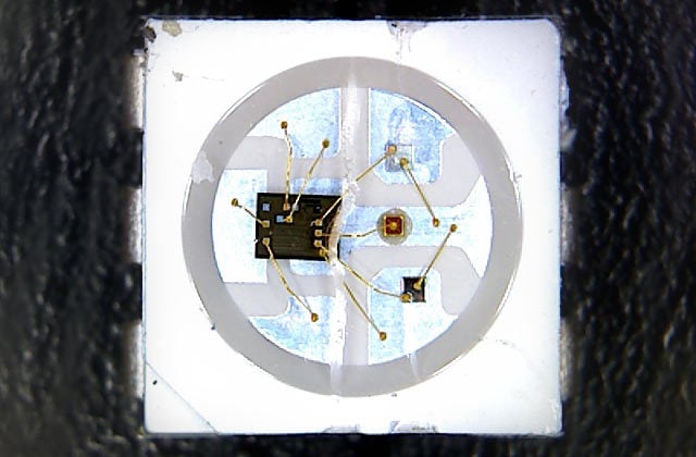
Image of NeoPixel from Adafruit
"The WS2812 Integrated Light Source — or NeoPixel in Adafruit parlance — is the latest advance in the quest for a simple, scalable and affordable full-color LED. Red, green and blue LEDs are integrated alongside a driver chip into a tiny surface-mount package controlled through a single wire. They can be used individually, chained into longer strings or assembled into still more interesting form-factors."
Connect up the circuit below using your Arduino MKR1010 and the Adafruit Neopixel Strip.
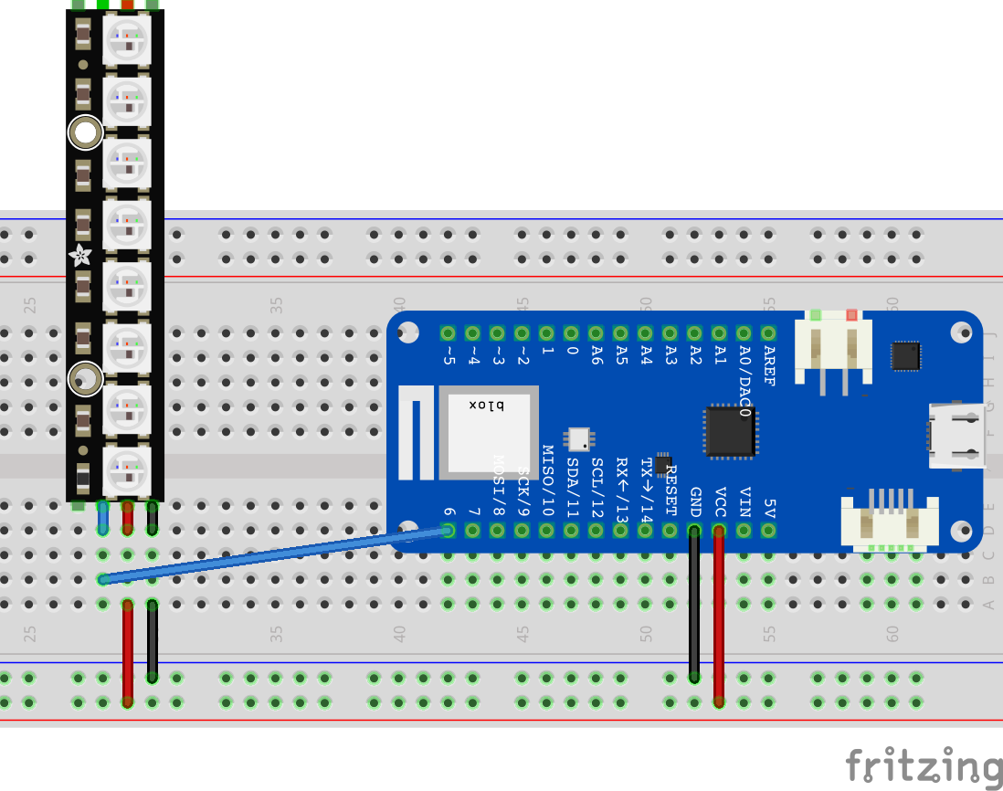
The red wires are supplying 5V to the lights along with the black ground wires completeing the circuit. In this simple example we are ok to use the power supply from the Arduino. But note the Arduino can only supply enough current (500mA) for a small number of Neo Pixel LEDS (each LED "pixel" can draw around 60mA at max brightness). For bigger installations, like Vespera, we use seperate power supplies to drive the LED's.
The blue wire is connected to digital pin 6 and is used to send data to the neopixel strip. Controllers on the neopixel strip are then converting those control signals into values to turn the leds on / off. The NeoPixel library introduced in the next page abstracts away the complexity of that control.
This basic sketch provides an example of how to send individual RGB (red, green, blue) values to each of the LEDs on the strip. The source is in CASA0014 Github.
#include <Adafruit_NeoPixel.h>

#define NEOPIXEL_PIN 6
#define NUMPIXELS 8

int red, blue, green = 0;

// Declare NeoPixel strip object (ie set it up):
Adafruit_NeoPixel pixels = Adafruit_NeoPixel(NUMPIXELS, NEOPIXEL_PIN, NEO_GRB + NEO_KHZ800);
// Argument 1 = Number of pixels in NeoPixel strip
// Argument 2 = Arduino pin number (most are valid)
// Argument 3 = Pixel type flags, add together as needed:
//   NEO_KHZ800  800 KHz bitstream (most NeoPixel products w/WS2812 LEDs)
//   NEO_KHZ400  400 KHz (classic 'v1' (not v2) FLORA pixels, WS2811 drivers)
//   NEO_GRB     Pixels are wired for GRB bitstream (most NeoPixel products)
//   NEO_RGB     Pixels are wired for RGB bitstream (v1 FLORA pixels, not v2)
//   NEO_RGBW    Pixels are wired for RGBW bitstream (NeoPixel RGBW products)


void setup() {
  pixels.begin();           // INITIALIZE NeoPixel strip object (REQUIRED)
  pixels.show();            // Turn OFF all pixels ASAP
  pixels.setBrightness(50); // Set BRIGHTNESS to about 1/5 (max = 255)
}

void loop() {

  // On each loop we want to set the colour for each pixel on the neopixel strip
  // So we loop through each one in turn, get a random RGB value and set the pixel
  for(int i=0; i<NUMPIXELS; i++) {

    red = random(0, 5) * 50;    // random() takes two numbers in a range and returns
    green = random(0, 5) * 50;  // a random value between, we then multiply that by 50
    blue = random(0, 5) * 50;   // so that we get seperation between the colours

    pixels.setPixelColor(i, red, green, blue);
  }

  // now the pixel values have been updated in memory we need to send them to the neopixel
  pixels.show();
  delay(300);

}
We import the Adafruit_NeoPixel library and declare an object called pixels to send messages to the neopixel strip. Since there are multiple types of Neopixel strips that can be used we can pass in a number of variables to declare which type we are using. Take a look at the three arguments that are passed in to the declaration.
In the Setup we initialise the pixel strip, run pixels.show to make sure all pixels are turned off and then reduce the brightness of all the LED's since they are so bright! Even in day light!
In the loop we are running through a "for" loop to set each of the 8 pixels in the strip. Remember we count from 0 in code (ie 0 to 7 in this case). In each of the for loops we select a random number between 0 and 255 and set that as the value for the seperate RGB values. We then write those values into memory using the pixels.setPixelColor function.
The final step after the for loop is to send the values in memory to the pixel strip using the function pixels.show(). We then wait for a little while before returning back to the top of the loop and starting over again.
We now need to combine our knowledge of connecting a MKR1010 to WiFi and sending MQTT messages in the WebLED tutorial with the information on how to write RGB values to NeoPixels to create a sketch that will send RGB values to Vespera.
Since we cannot all send messages to Vespera at the same time (whose RGB values would we use?) we will use a different topic for each person. The topic values are in this Google Sheet You can then use the Lumi web app to select your MQTT topic and see the results of your messages. (Note: code for Lumi is available on CASA0014 GitHub)
Screenshot of Lumi webpage showing current live data being sent to Vespera.
First up create a new sketch that connects your MKR1010 to WiFi and the MQTT broker.
Once you are happy that is connecting over wifi and connecting to the MQTT broker you can add the following code snippets to publish your first message.
Make sure you have updated the topic to your own from the Google Sheet.
// Make sure to update your lightid value below with the one you have been allocated
String lightId = "0"; // the topic id number or user number being used.

// Here we define the MQTT topic we will be publishing data to
String mqtt_topic = "student/CASA0014/luminaire/" + lightId;
You also need to set up some variables that are specific to the number of LED's in Vespera and a byte array to hold the RGB values.
// NeoPixel Configuration - we need to know this to know how to send messages
// to vespera
const int num_leds = 72;
const int payload_size = num_leds * 3; // x3 for RGB

// Create the byte array to send in MQTT payload this stores all the colours
// in memory so that they can be accessed in for example the rainbow function
byte RGBpayload[payload_size];
Note: the RGBpayload variable is an array that contains all the RGB values for each of the 72 LED's in Vespera. Every time we send a message to Vespera we send all the values. We do this to make updating the lights quicker and simpler.
Next up create a new function (below the loop function) that will send the RGBpayload array to Vespera using MQTT.
// Function to update the R, G, B values of a single LED pixel
// RGB can a value between 0-254, pixel is 0-71 for a 72 neopixel strip
void send_RGB_to_pixel(int r, int g, int b, int pixel) {
  // Check if the client is connected before publishing
  if (client.connected()) {
    // Update the byte array with the specified RGB color pattern
    RGBpayload[pixel * 3 + 0] = (byte)r; // Red
    RGBpayload[pixel * 3 + 1] = (byte)g; // Green
    RGBpayload[pixel * 3 + 2] = (byte)b; // Blue

    // Publish the byte array
    client.publish(mqtt_topic.c_str(), RGBpayload, payload_size);

    Serial.println("Published whole byte array after updating a single pixel.");
  } else {
    Serial.println("MQTT client not connected, cannot publish from *send_RGB_to_pixel*.");
  }
}
This function takes in 4 arguments, the RGB values (0-255) and the pixel number (0-71). It then updates the RGBpayload array with the new RGB values for that pixel and sends the whole array to Vespera using MQTT.
Lastly we need to call this function from the loop function. The example below shows a simple way to send "red" values to each pixel in turn.
void loop() {
  // Reconnect if necessary
  if (!client.connected()) {
    reconnectMQTT();
  }

  if (WiFi.status() != WL_CONNECTED){
    startWifi();
  }
  // keep mqtt alive
  client.loop();

  for(int pixel = 0; pixel < num_leds; pixel++){
    send_RGB_to_pixel(255,0,0,pixel); // send red to each pixel in turn
    delay(100);
  }

}
Compile and upload the sketch to your MKR1010 and then open the Serial Monitor. You should see messages indicating that the MQTT messages are being sent. If you have selected your topic in the Lumi web app you should see the lights on the web page changing to red in turn.
You should now have a working sketch that is sending RGB values to Vespera.
The two extra functions below give some more examples of how to set the RGB values in different ways. You can copy and paste these functions into your sketch and call them from the loop function to see how they work.
The function below sets all the pixels to black ("off"). This is handy if you want clear all the values on Vespera before sending new ones.
void send_all_off() {
  // Check if the client is connected before publishing
  if (client.connected()) {
    // Fill the byte array with the specified RGB color pattern
    for(int pixel=0; pixel < num_leds; pixel++){
      RGBpayload[pixel * 3 + 0] = (byte)0; // Red
      RGBpayload[pixel * 3 + 1] = (byte)0; // Green
      RGBpayload[pixel * 3 + 2] = (byte)0; // Blue
    }
    // Publish the byte array
    client.publish(mqtt_topic.c_str(), RGBpayload, payload_size);

    Serial.println("Published an all zero (off) byte array.");
  } else {
    Serial.println("MQTT client not connected, cannot publish from *send_all_off*.");
  }
}
You would call this function from the loop function like this:
  send_all_off();
  delay(2000); // maybe add a delay so you can see that the lights did go off
The function below creates a random colour for each pixel and sends the whole array to Vespera which is handy for seeing if pixel values are being updated (when we send a static colour such as red it is hard to see if the values are being updated).
void send_all_random() {
  // Check if the client is connected before publishing
  if (client.connected()) {
    // Fill the byte array with the specified RGB color pattern
    for(int pixel=0; pixel < num_leds; pixel++){
      RGBpayload[pixel * 3 + 0] = (byte)random(50,256); // Red - 256 is exclusive, so it goes up to 255
      RGBpayload[pixel * 3 + 1] = (byte)random(50,256); // Green
      RGBpayload[pixel * 3 + 2] = (byte)random(50,256); // Blue
    }
    // Publish the byte array
    client.publish(mqtt_topic.c_str(), RGBpayload, payload_size);

    Serial.println("Published an all random byte array.");
  } else {
    Serial.println("MQTT client not connected, cannot publish from *send_all_random*.");
  }
}
You could call this function from the loop function like this:
  for(int loop = 0; loop < 50; loop++){
    send_all_random();
    delay(100);
  }
This would send 50 random colour patterns to Vespera with a 100ms delay between each one creating a quick animation.
A complete code sample for this sketch is in CASA0014 Github
The goal of your assessment is to use a local sensor on a MKR1010 to update Vespera. Play with the code on the previous page to explore different ways to send colours to the Lumi Web app.
How can you change the RGB values in patterns that look useful or interesting? Will you try and display some information or a status on them? Or will you show a warning or alarm? Or maybe a colour change that is reacting to the environment? Or something that is fun to play with?
Lots of information and past projects using Neopixels exist on the internet. Do research to see what approaches others have taken to using pixels to convey information.
The Adafruit Neopixel Uberguide is a great place to start to get a deeper understanding of how Neopixels work. Take a look at the Arduino section of the guide and some of the examples in the library (File > Examples > Adafruit Neopixels)
In the example for sending RGB values to Vespera the code is split into multiple files. This is a common approach to organising code into smaller chunks that are easier to understand and maintain.
For the arduino_secrets.h file we need to add an include statement at the top of the main .ino file but with the connections.ino file we don't. Why is that?
In Arduino, you need to use #include for .h (header) files because they contain function declarations and variable definitions that allow your main .ino file to know what exists in other code files. You don't need to explicitly include .ino files because the Arduino IDE automatically concatenates all .ino files in a sketch folder into a single file before compiling.
How Arduino Compiles Your Sketch:
The Arduino IDE's build process simplifies things for you. When you have multiple files in a sketch folder, it works like this:
Concatenation: The IDE finds all the .ino files in your sketch folder and combines them into one large .cpp file in a specific order. The main sketch file (the one with the same name as the folder) is placed first.
Function Prototypes: The IDE then automatically generates function prototypes for all the functions you've defined in the .ino files and inserts them at the top of the concatenated file. This is a common point of confusion for new users, as this automated process is why you can call a function before it's defined in your sketch without getting a compiler error.
Compilation: The single, pre-processed .cpp file is then compiled into machine code.
This behind-the-scenes process is why you don't need to use #include for your other .ino files. The compiler effectively sees them as one big file.
Why Header Files (.h) are Different
Header files (.h) are used for a different purpose, typically for code that is not an .ino file, such as a C++ class definition or a library. They contain function prototypes, variable declarations, and other necessary information that the compiler needs to "see" before it can call a function or use a variable from a different compilation unit. When you use #include "my_file.h", you are telling the preprocessor to copy the contents of my_file.h directly into your current file. This is standard C++ practice and is essential when using external libraries or your own custom classes.