In this workshop you will learn how to:
- Write RGB colour values to a Neopixel strip connected to an Arduino MKR1010
This example is aimed at helping kickstart ideas on how you can send colour values to the Chrono Lumina display. Working directly with the neopixel strip will allow you to test out ideas locally before using the network based display.

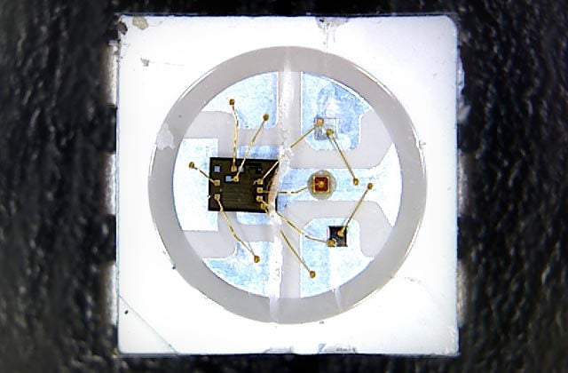
Image of NeoPixel from Adafruit
"The WS2812 Integrated Light Source — or NeoPixel in Adafruit parlance — is the latest advance in the quest for a simple, scalable and affordable full-color LED. Red, green and blue LEDs are integrated alongside a driver chip into a tiny surface-mount package controlled through a single wire. They can be used individually, chained into longer strings or assembled into still more interesting form-factors."
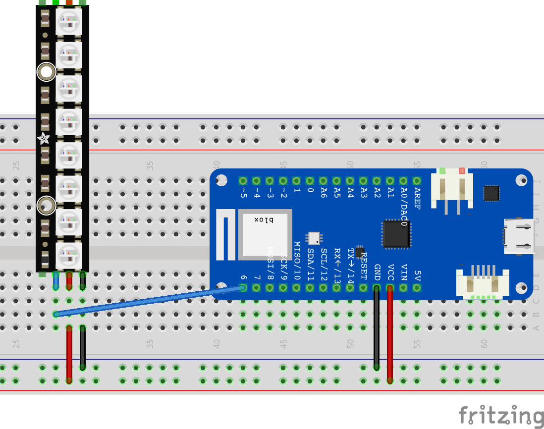
Connect up the circuit below using your Arduino MKR1010 and the Adafruit Neopixel Strip.

The red wires are supplying 5V to the lights along with the black ground wires completeing the circuit. In this simple example we are ok to use the power supply from the Arduino. But note the Arduino can only supply enough current (500mA) for a small number of Neo Pixel LEDS (each LED "pixel" can draw around 60mA at max brightness). For bigger installations, like Chrono Lumina, we use seperate power supplies to drive the LED's.
The blue wire is connected to digital pin 6 and is used to send data to the neopixel strip. Controllers on the neopixel strip are then converting those control signals into values to turn the leds on / off. The NeoPixel library introduced in the next page abstracts away the complexity of that control.
This basic sketch provides an example of how to send individual RGB (red, green, blue) values to each of the LEDs on the strip. The source is in CASA0014 Github.
#include <Adafruit_NeoPixel.h>

#define NEOPIXEL_PIN 6
#define NUMPIXELS 8

int red, blue, green = 0;

// Declare NeoPixel strip object (ie set it up):
Adafruit_NeoPixel pixels = Adafruit_NeoPixel(NUMPIXELS, NEOPIXEL_PIN, NEO_GRB + NEO_KHZ800);
// Argument 1 = Number of pixels in NeoPixel strip
// Argument 2 = Arduino pin number (most are valid)
// Argument 3 = Pixel type flags, add together as needed:
//   NEO_KHZ800  800 KHz bitstream (most NeoPixel products w/WS2812 LEDs)
//   NEO_KHZ400  400 KHz (classic 'v1' (not v2) FLORA pixels, WS2811 drivers)
//   NEO_GRB     Pixels are wired for GRB bitstream (most NeoPixel products)
//   NEO_RGB     Pixels are wired for RGB bitstream (v1 FLORA pixels, not v2)
//   NEO_RGBW    Pixels are wired for RGBW bitstream (NeoPixel RGBW products)


void setup() {
  pixels.begin();           // INITIALIZE NeoPixel strip object (REQUIRED)
  pixels.show();            // Turn OFF all pixels ASAP
  pixels.setBrightness(50); // Set BRIGHTNESS to about 1/5 (max = 255)
}

void loop() {

  // On each loop we want to set the colour for each pixel on the neopixel strip
  // So we loop through each one in turn, get a random RGB value and set the pixel
  for(int i=0; i<NUMPIXELS; i++) {

    red = random(0, 5) * 50;    // random() takes two numbers in a range and returns
    green = random(0, 5) * 50;  // a random value between, we then multiply that by 50
    blue = random(0, 5) * 50;   // so that we get seperation between the colours

    pixels.setPixelColor(i, red, green, blue);
  }

  // now the pixel values have been updated in memory we need to send them to the neopixel
  pixels.show();
  delay(300);

}
We import the Adafruit_NeoPixel library and declare an object called pixels to send messages to the neopixel strip. Since there are multiple types of Neopixel strips that can be used we can pass in a number of variables to declare which type we are using. Take a look at the three arguments that are passed in to the declaration.
In the Setup we initialise the pixel strip, run pixels.show to make sure all pixels are turned off and then reduce the brightness of all the LED's since they are so bright! Even in day light!
In the loop we are running through a "for" loop to set each of the 8 pixels in the strip. Remember we count from 0 in code (ie 0 to 7 in this case). In each of the for loops we select a random number between 0 and 255 and set that as the value for the seperate RGB values. We then write those values into memory using the pixels.setPixelColor function.
The final step after the for loop is to send the values in memory to the pixel strip using the function pixels.show(). We then wait for a little while before returning back to the top of the loop and starting over again.
The goal of your assessment is to use a local sensor on a MKR1010 to update some lights on remote NeoPixels. Play with the code on the previous page to explore different ways to send colours to the neopixel strip. How can you change the RGB values in patterns that look useful? Will you try and display some information or a status on them? Or will you show a warning or alarm? Or maybe a colour change that is reacting to the environment?
Lots of information and past projects using Neopixels exist on the internet. Do research to see what approaches others have taken to using pixels to convey information.
The Adafruit Neopixel Uberguide is a great place to start to get a deeper understanding of how Neopixels work. As a minimum look at the Arduino section of the guide and some of the examples in the library (File > Examples > Adafruit Neopixels)
In the next workshop we will explore the MQTT interface to Vespera.