In this workshop you will learn:
- how to set-up the Arduino environment and connect your board
- how to organise your code in Arduino
- how to flash a light in Arduino
This workshop is broken down into a few phases:
- setting up your environment for coding and getting the board physically connected
- getting familiar with the Arduino environment
- building the blink sketch
Download and install the Arduino IDE Click the JUST DOWNLOAD link to the left of the CONTRIBUTE & DOWNLOAD button. Once downloaded follow the instructions to install.
First launch the Arduino IDE.
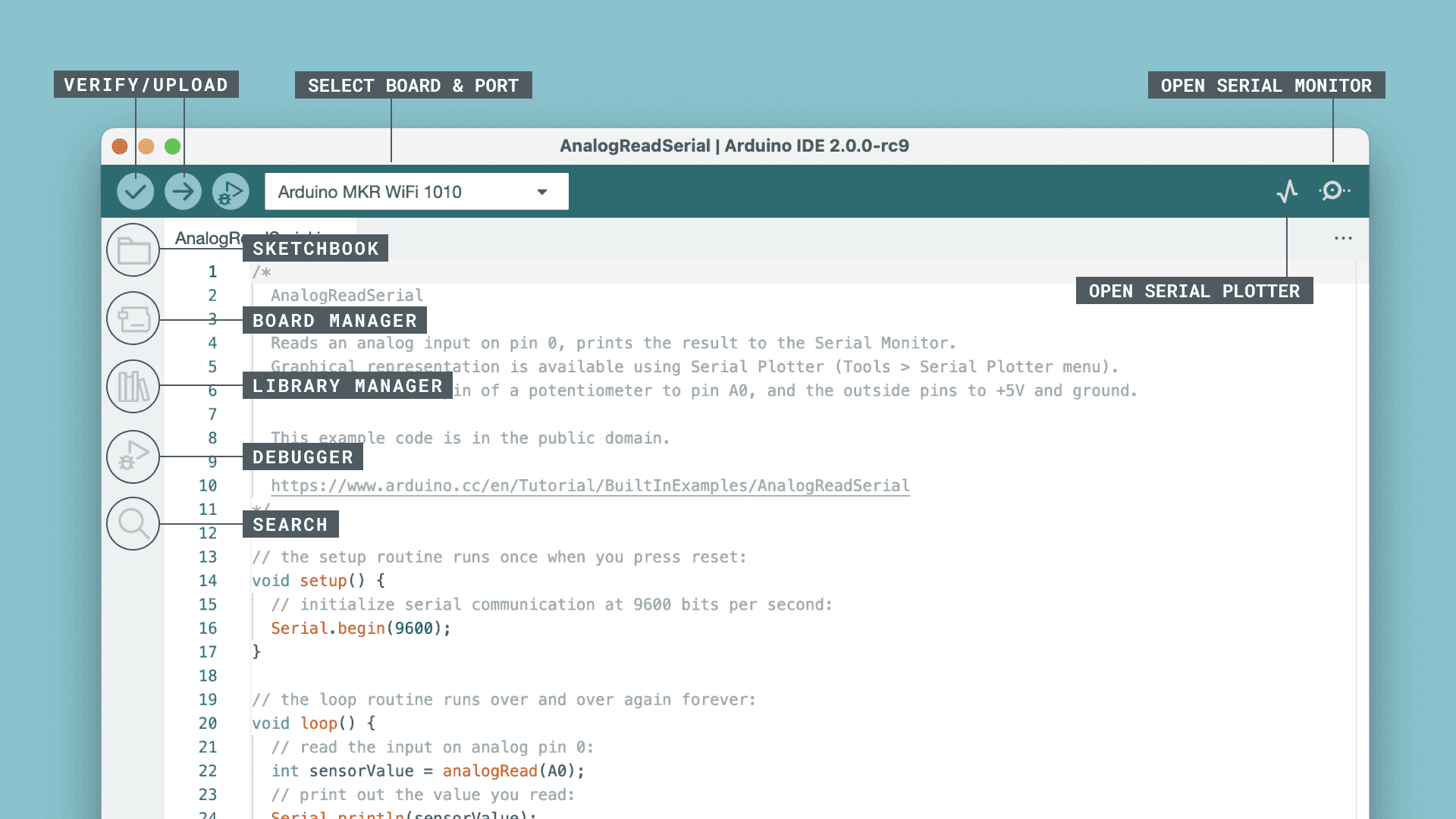
The screenshot below (from a Mac) shows an overview of the main elements of the Arduino 2.0 IDE you will work with today.
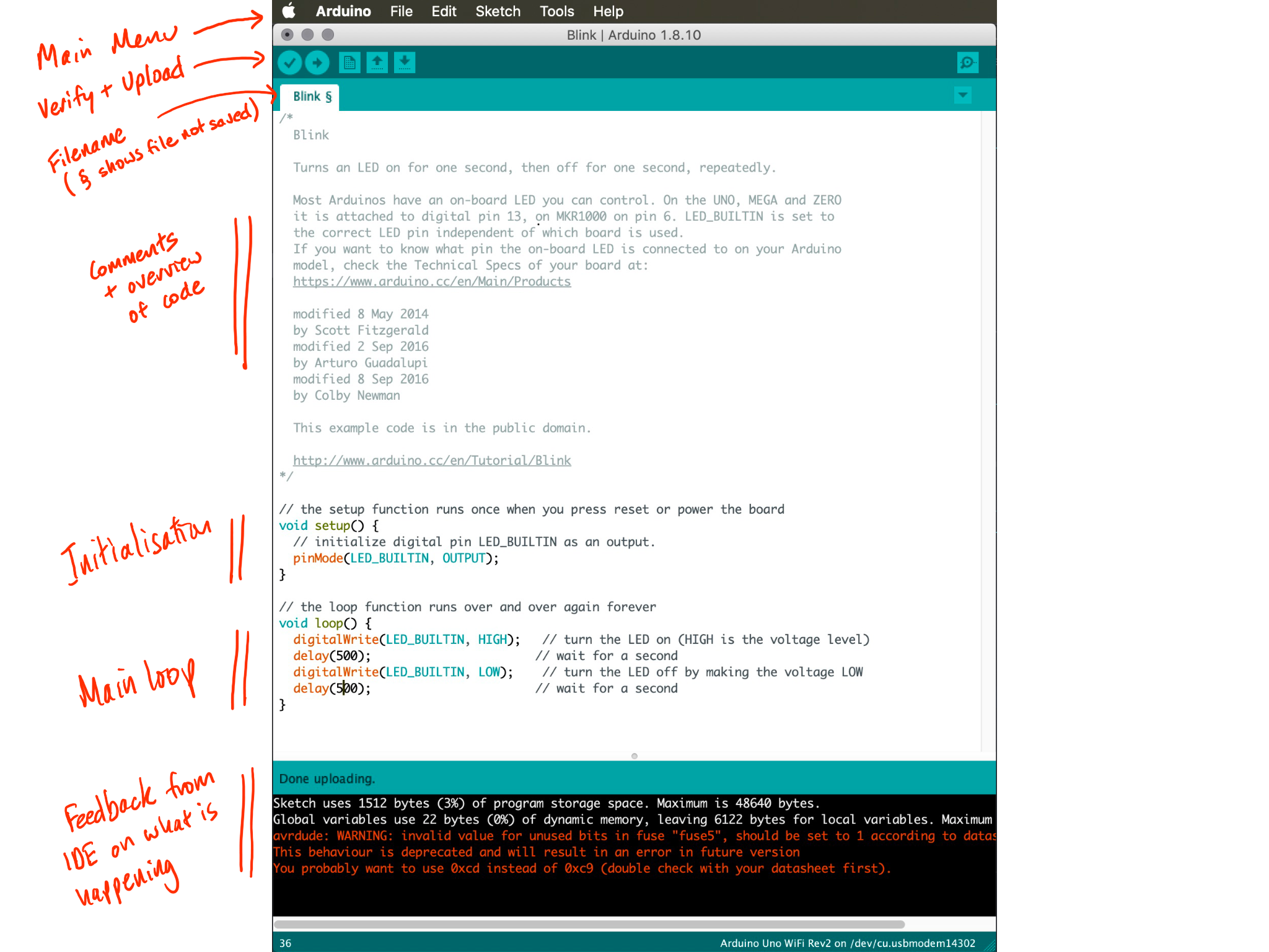
The screenshot below (from a Mac) shows an overview of the main elements of the Arduino 1.8 IDE. The notes in red highlight the main elements of the top navigation, the main body of the code and the message window at the bottom.
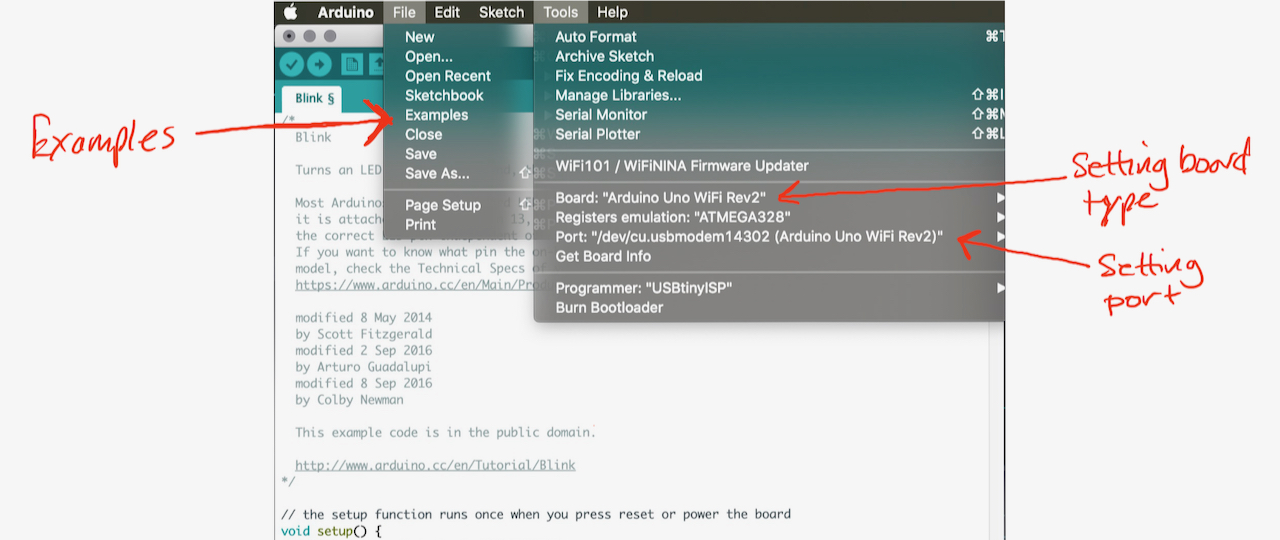
If you expand the File and Tools main menus. In the File menu Arduino ships with a bunch of useful examples to get you started and to help you explore. In the Tools menu there are a couple of menu items that you will need to get familiar with: the Board item shows you which kind of Arduino you are currently trying to program (in this case an Arduino Uno WiFi Rev2) and the Port item which shows you which USB port the device is connected to. In this case it is showing the port on a mac at /dev/cu.usbmodem14302 - if I was on a Windows machine it might say COM4.
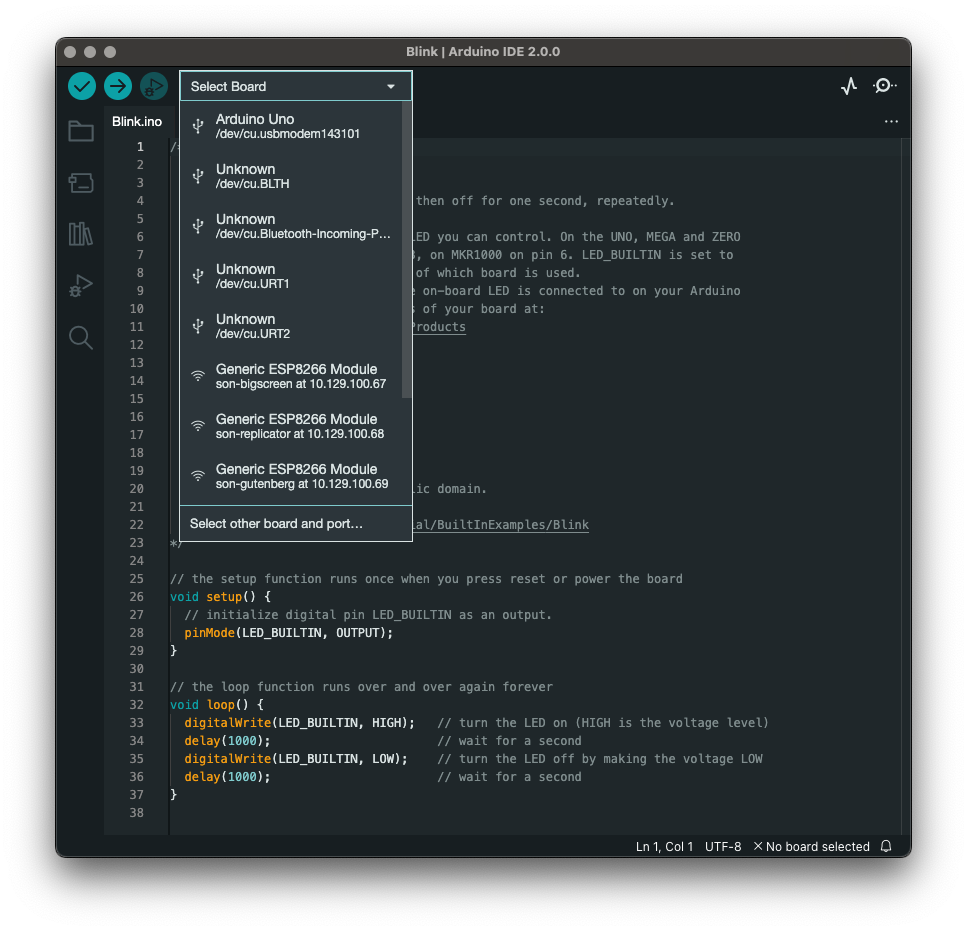
In the new IDE you can also the quick drop down to select your board.
Further resources on the v2.0 IDE are available on the Arduino IDE 2 Tutorials page if you want to do a deeper dive into what is where.
In the next step we will upload are first Sketch and get the Arduino doing something for us.
To familiarise yourself with the Arduino platform load a basic blink sketch from the examples that are distributed with the Arduino IDE.
First off - plug in your Arduino to a USB port!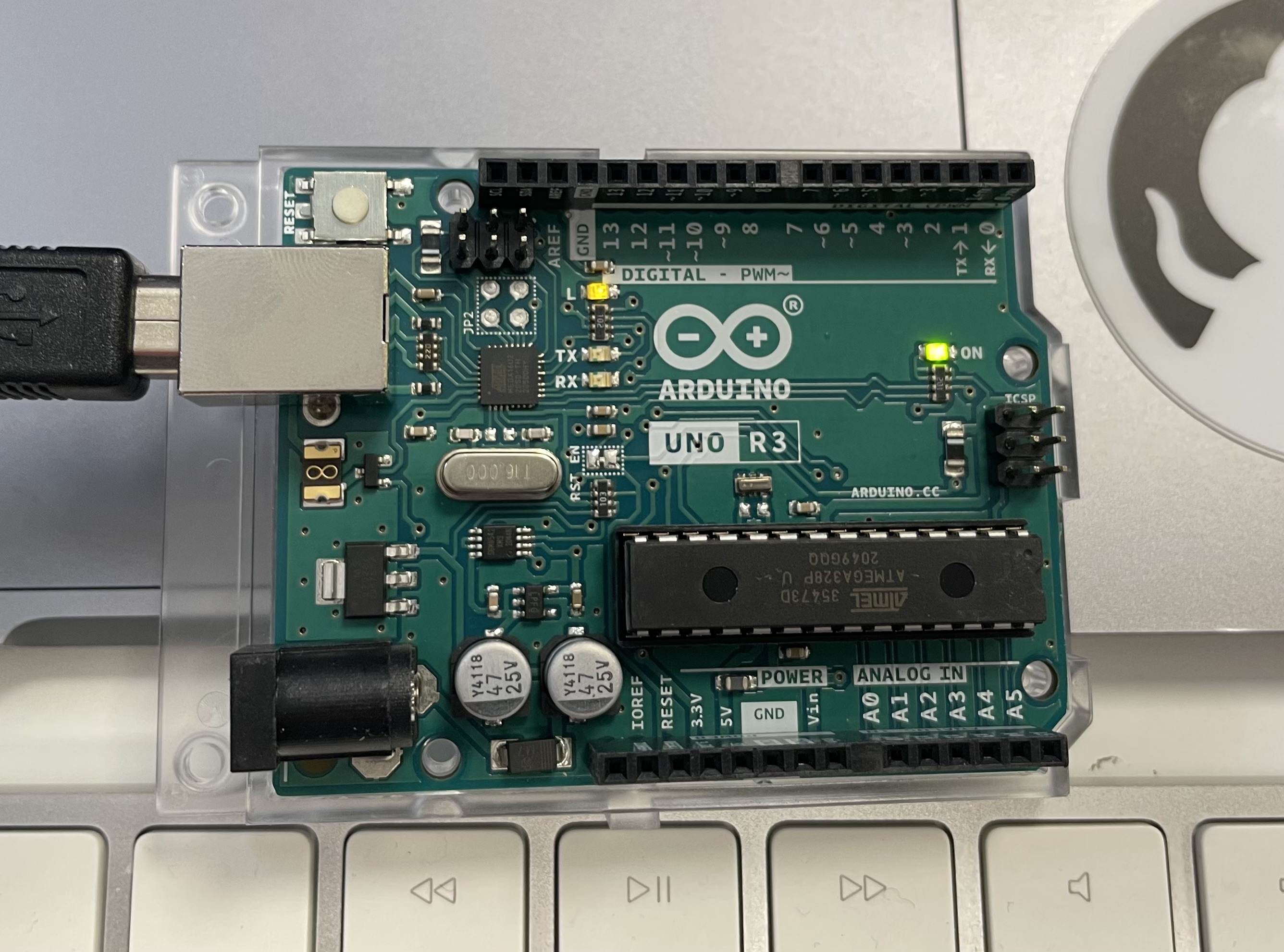
Load the following sketch:File -> Examples -> Basics -> Blink
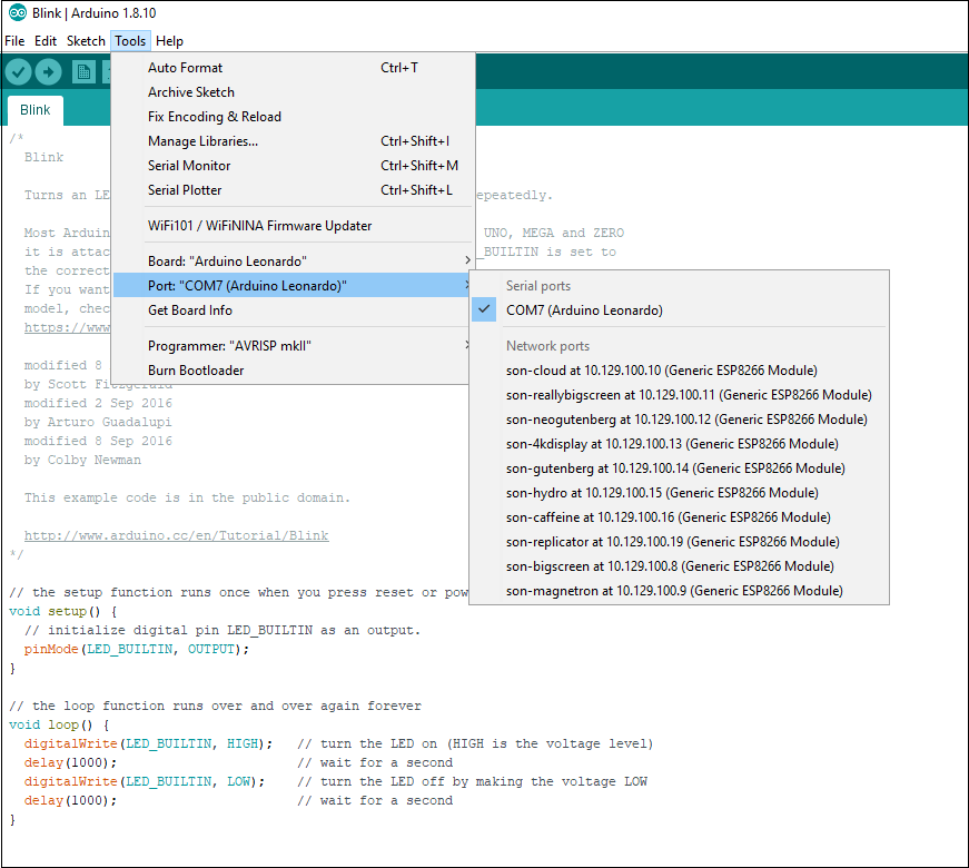
Ensure board set to the Arduino you are using (e.g. Arduino Uno):Tool -> Boards -> Arduino AVR boards -> Arduino Uno
Ensure the correct port for the Arduino Uno has been selected:Tools -> Port:... as shown in the screenshot below for Windows:
and for Mac:
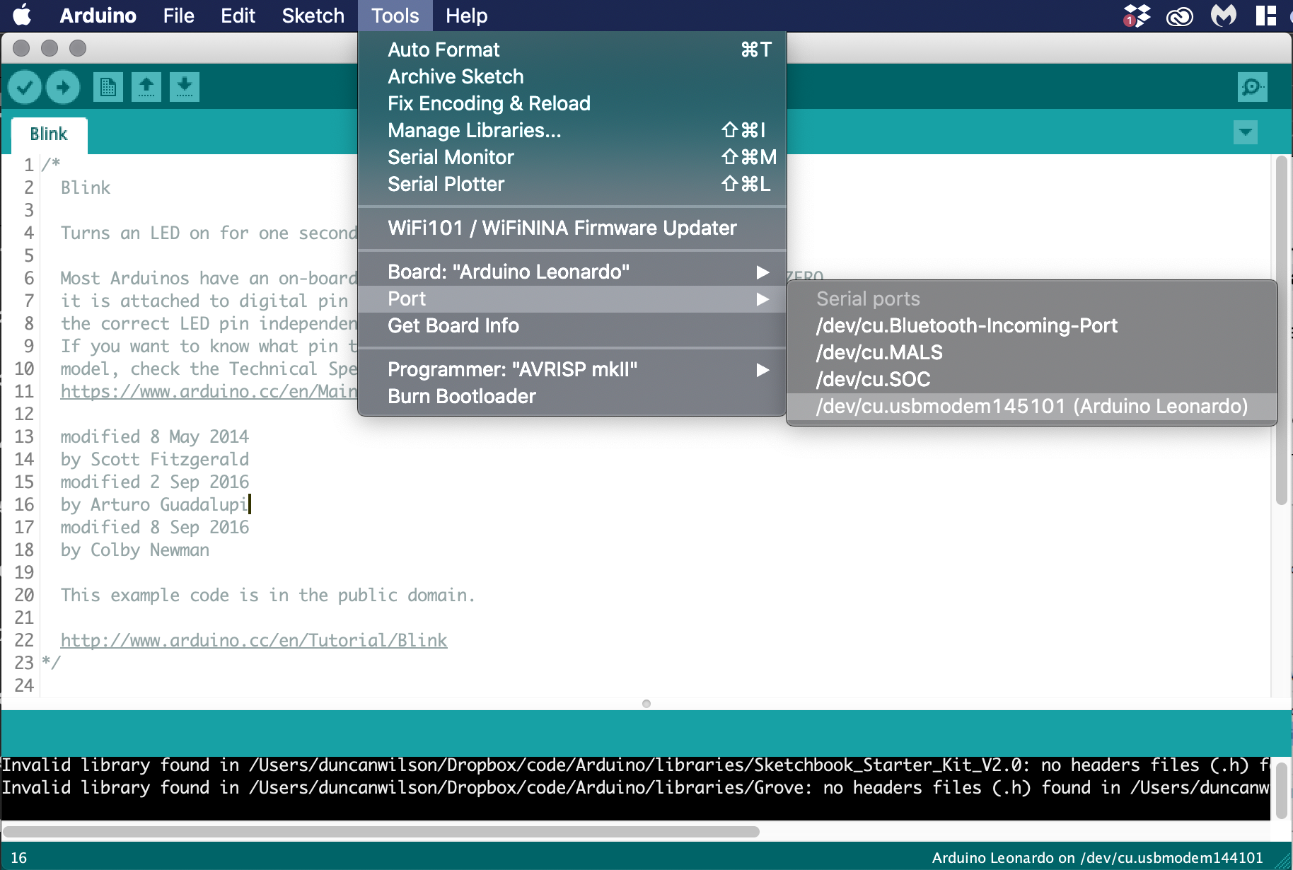
Note that the your board may connect on a different COM port to the one shown in the screenshot above (COM7) and will be called Arduino Uno (not Leonardo).
Now save and upload the sketch using the upload button (as shown below).
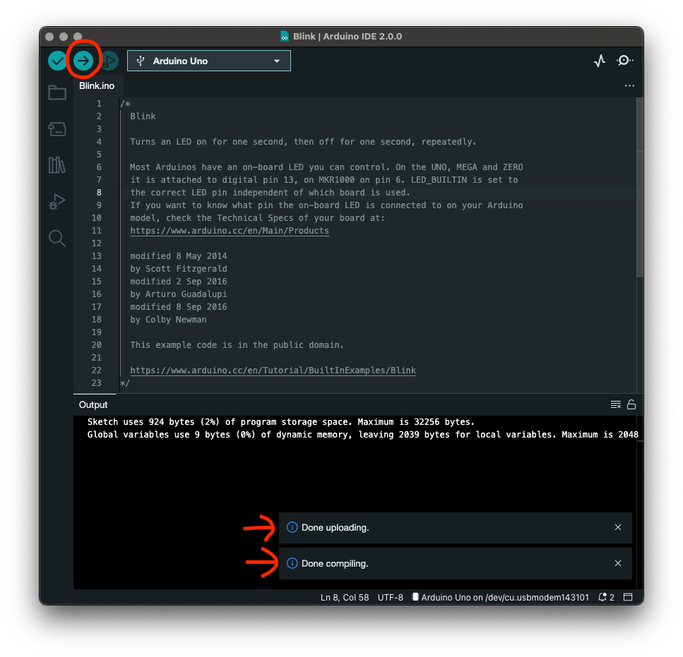
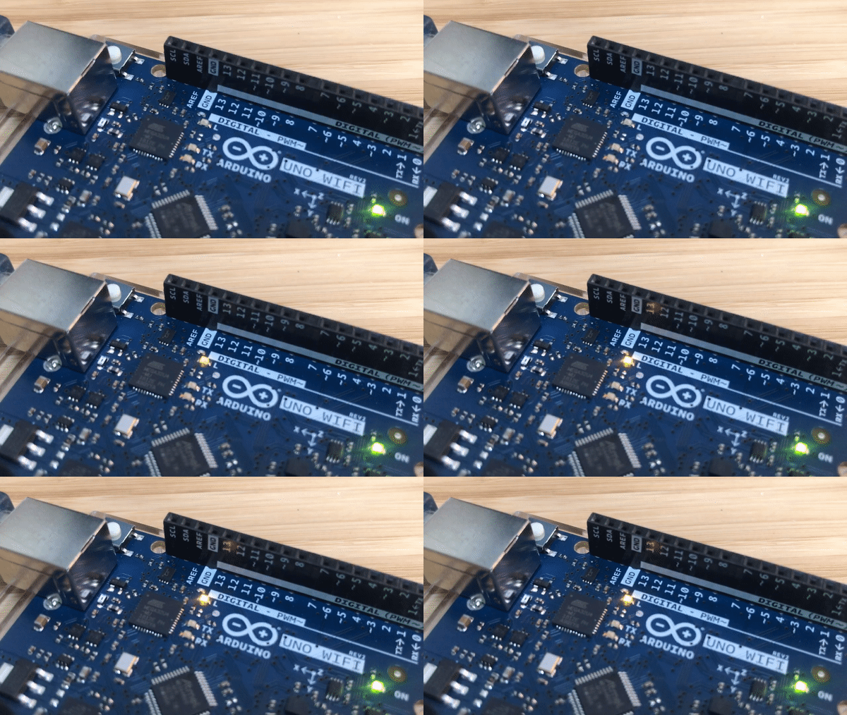
If you look at the Arduino board you should see the built in LED blinking every second.
Next up we will run through the anatomy of a sketch (the setup and the loop) and then return to a bit of house keeping and work out where to store code on our computers.
The light is flashing, but what was going on?
The beauty of microcontrollers are the simplicity of how programmes run. All Arduino sketches have two primary sections - void setup() which is executed once as the device is powered up, and void loop() which the continually runs until power is removed. Once the code within the latter function gets to the bottom it simply returns back to the start of the function and starts again - hence the name loop.
We look at each in turn:
void setup() {
  pinMode(LED_BUILTIN, OUTPUT);
}
In your blink sketch setup() calls just one function pinMode(). This function defines whether a pin you are connecting to is either an input or an output.
LED_BUILTIN is a variable within Arduino that defines which PIN the onboard LED is on. Traditionally this was on PIN 13 but some newer boards use PIN 6. To make it easier to manage this variable is defined by the board configuration so we don't have to think about it.
OUTPUT means that PIN is acting as an output ie current flows through it to drive an LED.
void loop() {
  digitalWrite(LED_BUILTIN, HIGH);   // turn the LED on (HIGH is the voltage level)
  delay(500);                       // wait for a second
  digitalWrite(LED_BUILTIN, LOW);    // turn the LED off by making the voltage LOW
  delay(500);                       // wait for a second
}
In the loop() function we have 4 steps:
- the
digitalWrite()function changes a digital pin with a value ofHIGHorLOW. In this case we are setting the pin located atLED_BUILTIN(digital pin 13 on the Uno) to a value ofHIGH. This sets the voltage level high and ‘turns on' the LED. - the
delay()function pauses the sketch for a defined number of milliseconds. In this case we are pausing for 500 milliseconds, or half a second. - the value of
LED_BUILTINis now being set toLOW. This ‘turns off' the LED. - finally we have another pause of half a second.
At the end of the loop() function the program returns back to the start of the loop() function and repeats. The structure of all sketches follow the same pattern.
The beauty of Arduino is there are loads of examples on the internet for you to experiment with. Most things you can imagine have probably already been implemented.
The Arduino IDE can be configured using the preferences section of the application. Equally if you have another code editor of choice they often have plugins to support Arduino sketch development. The Arduino page here has some guidance on tweaking your environment.
The last thing we encourage you to think about at this stage in setting up your Arduino coding environment is the location where you will store files. By default Arduino stores files in your /Documents folder on a Mac or /My Documents folder on Windows and then in a subfolder called /Arduino. It is worth thinking about how you will organise and back up all your code through the rest of the year.
In the next section we will focus on how to share code and collaborate with others.
Now that the housekeeping is sorted we can return to making some lights flash. Make sure your Arduino code you have been working on is in the folder you set-up in the previous step (or if you want to start fresh open up the blink example File>Examples>01.Basics>Blink and save a copy of it in your folder).
In our initial sketch we flashed a builtin LED on pin 13. Next we will start using the Pins on the Arduino to prototype our own circuit. The Arduino has a number of exposed female pins that allow you to quickly and easily plug in wires to connect sensors or actuators. A key part of the process of prototyping with microcontrollers is getting familiar with the input and output pins on the board you are using. As an example the standard Arduino has both digital and analog pins as shown in the diagram below from the Introduction to the Arduino Board webpage.
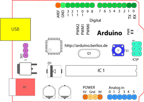
The green pins are digital (can be set hi or low). The blue ones are analog (using a 10-bit analog to digital converter reading a voltage between 0V and either 3.3V or 5V - hence converting to 0 to 1023 or 2^10). The orange ones are power and ground.
You will notice the diagram shows the board having 5V and 9V. This is due to it being an image of an early board and highlights an important lesson:
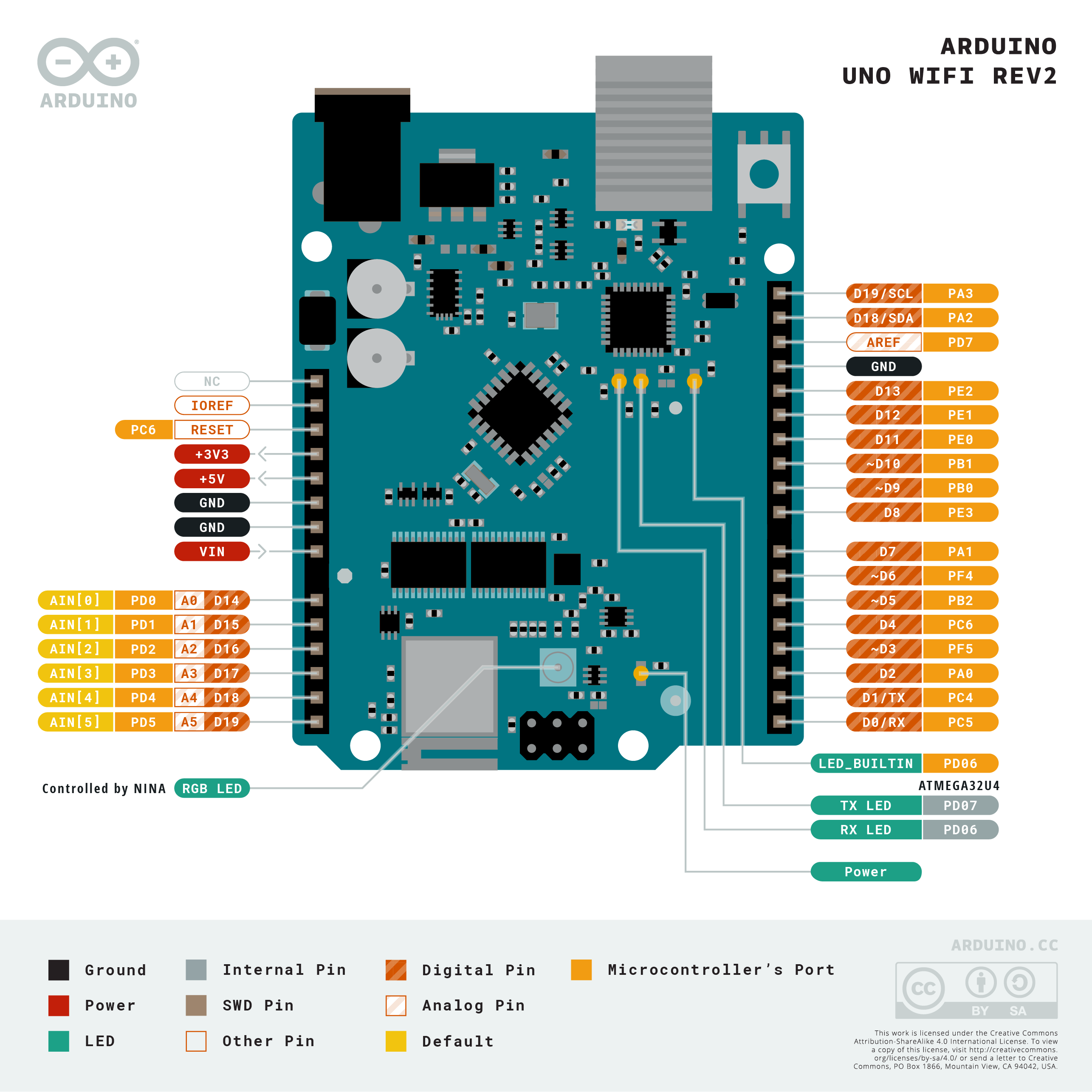
For example, in setting up this tutorial an Arduino Uno Wifi Rev2 was used and the reference sheet found by googling arduino+pin+layout+uno+wifi+r2 and if you compare the two diagrams you will notice some differences.
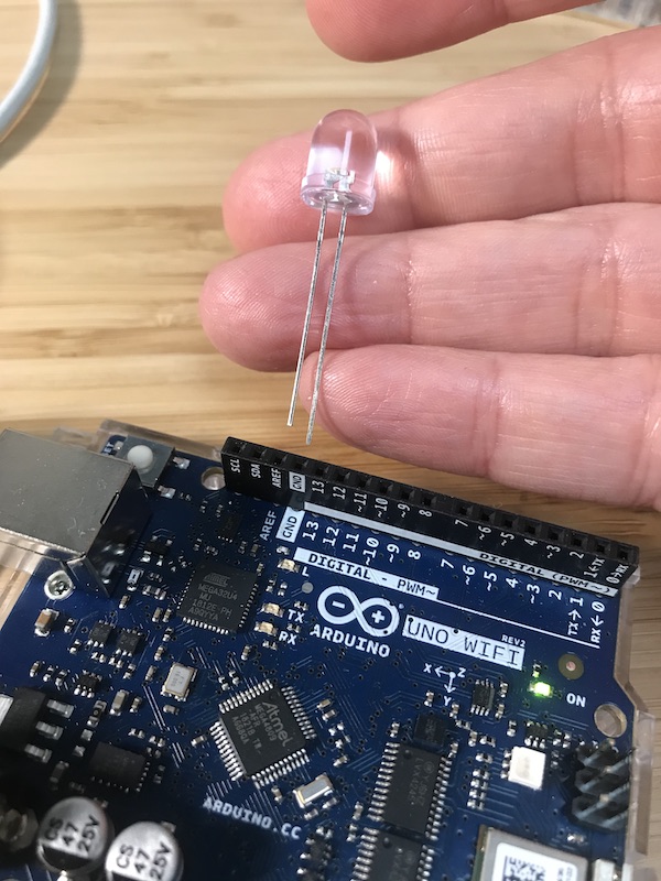
Whilst the BUILTIN LED is great for debugging and checking the state of programmes, we want to flash a ‘real' LED.
The simplest way we can do this is to add an LED directly into the pins. The positive of the LED goes into PIN13 the negative needs to go to GND or ground which is conveniently located alongside.
Upload the blink sketch to the board and you should now see the LED flashing. LED not flashing? Two things you can check are at the bottom of the page.
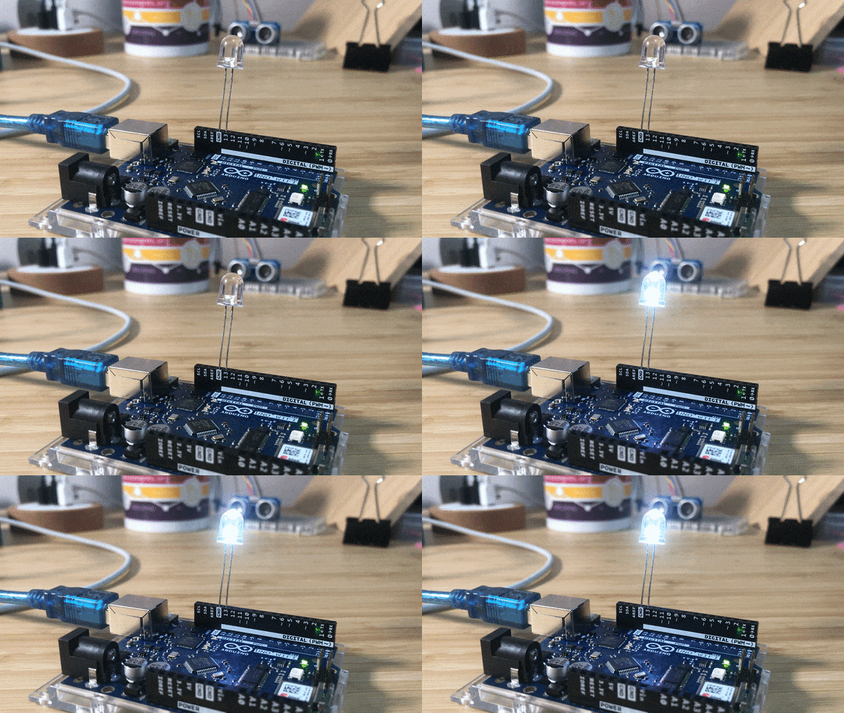
In future workshops we will delve into LEDs in more detail and will caution about short circuits etc. But for now you have completed the Hello Word of physical computing!
LED not flashing? This could either be because you have the long and short legs of the LED in the wrong pins, or you have defined your LED to be LED_BUILTIN rather than pin 13. Change all references to ‘LED_BUILTIN' below to ‘13'.
void setup() {
  // initialize digital pin LED_BUILTIN as an output.
  pinMode(LED_BUILTIN, OUTPUT);
}

// the loop function runs over and over again forever
void loop() {
  digitalWrite(LED_BUILTIN, HIGH);   // turn the LED on (HIGH is the voltage level)
  delay(1000);                       // wait for a second
  digitalWrite(LED_BUILTIN, LOW);    // turn the LED off by making the voltage LOW
  delay(1000);                       // wait for a second
}
Correct version when LED plugged into pin 13 and GND is:
void setup() {
  // initialize digital pin LED_BUILTIN as an output.
  pinMode(13, OUTPUT);
}

// the loop function runs over and over again forever
void loop() {
  digitalWrite(13, HIGH);   // turn the LED on (HIGH is the voltage level)
  delay(1000);                       // wait for a second
  digitalWrite(13, LOW);    // turn the LED off by making the voltage LOW
  delay(1000);                       // wait for a second
}
Now is a good time to save all your work.
To get up and running quickly we used all the default file locations for Arduino. As we are about to start a series of workshops to test out ideas it is useful to create a common location where you will store your sketches locally.
- Decide where you are going to store all your Arduino sketches on your local machine (Arduino defaults to
/users/username/Documents/Arduinoon a Mac but I save to a folder called/users/username/Dropbox/Code/Arduino- there is no right and wrong way to set this up - feel free to ask why I do it this way!). I have a folder in my Connected Environments folder called "workshops" where I store all the workshop examples from across all the CE modules I work on.
Well done! You have created your first physical prototype. In the final section we will point you towards some libraries you may want to explore to get started.
Computing is all about abstraction and decomposition, breaking tasks into small pieces to help make the overall picture easier to understand. Libraries are essentially programmes that other people have written so that you don't have to repeat what they have done, you can just start to work with their tools.
We will cover many Libraries as we go through the workshops but feel free to start exploring. If you browse to the Arduino Libraries reference you will see examples of where people have already written code so that you don't have to - for example, most sketches I wrote over the past year used the WiFi NINA library.
To install third party Libraries follow the guide on the Arduino reference page. We are particularly fond of the Adafruit NeoPixels Library