Create an account on the Things Network
Add your username to the Google sheet so that we can add you as a collaborator to our application.
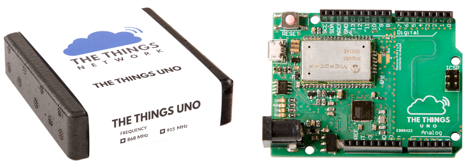
Now you will explore setting up the Arduino Things Uno board as a LoRa device.
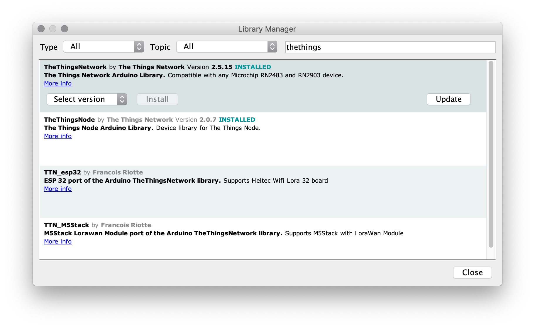
First, install the TheThingsNetwork library using the Libary Manager:Sketch -> Include library -> Manage Libraries
Load the following sketch:File -> Examples -> TheThingsNetwork -> DeviceInfo
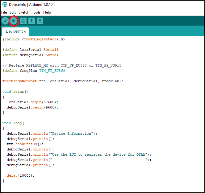
In the DeviceInfo sketch locate the line
#define freqPlan REPLACE_ME
and replace the phrase REPLACE_ME with TTN_FP_EU868
Next up we need to make sure the correct board and port are selected.
In the Arduino IDE, select Tools > Boards > Arduino Leonardo
Navigate to Tools > Port and select the port that identifies as Arduino Leonardo
Upload the sketch using the Upload button (as shown below)
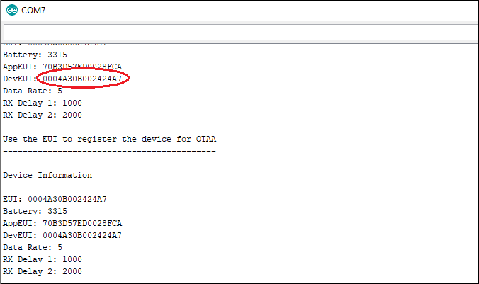
Open the Serial Monitor:Tools -> Serial Monitor
and copy the DevEUI value as shown below:
Now you will explore setting up the Arduino board as a LoRa device.
First, install the TheThingsNode library using the Libary Manager:Sketch -> Include library -> Manage Libraries
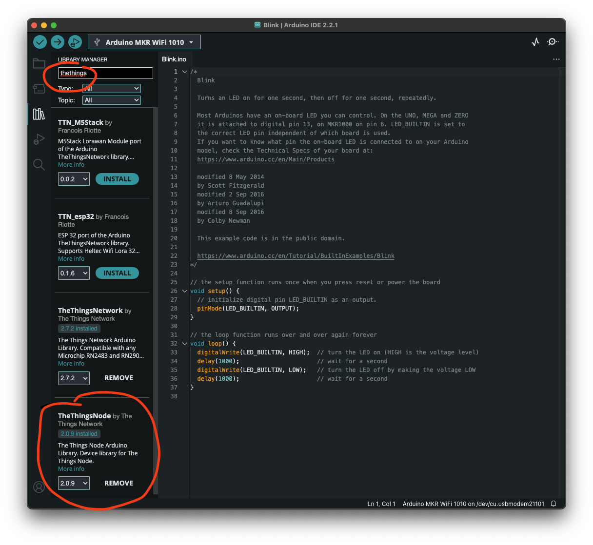
Load the following sketch:File -> Examples -> TheThingsNode -> DeviceInfo
In the DeviceInfo sketch locate the line
#define freqPlan REPLACE_ME
and replace the phrase REPLACE_ME with TTN_FP_EU868
Next up we need to make sure the correct board and port are selected.
The Things Node is a development board based on the SparkFun Pro Micro. To program the board through teh Arduino IDE we need to install some software so that Arduino can compile and install code on that specific device. To do this we need to add a new board manager. Follow these instructions to install the required dependencies
Once added into the settings file (if you are getting an error make sure the URL is on a different line - click the button to the right of the URL field) then in the Boards Manager search for SparkFun Pro Micro and install the SparkFun AVR Boards.
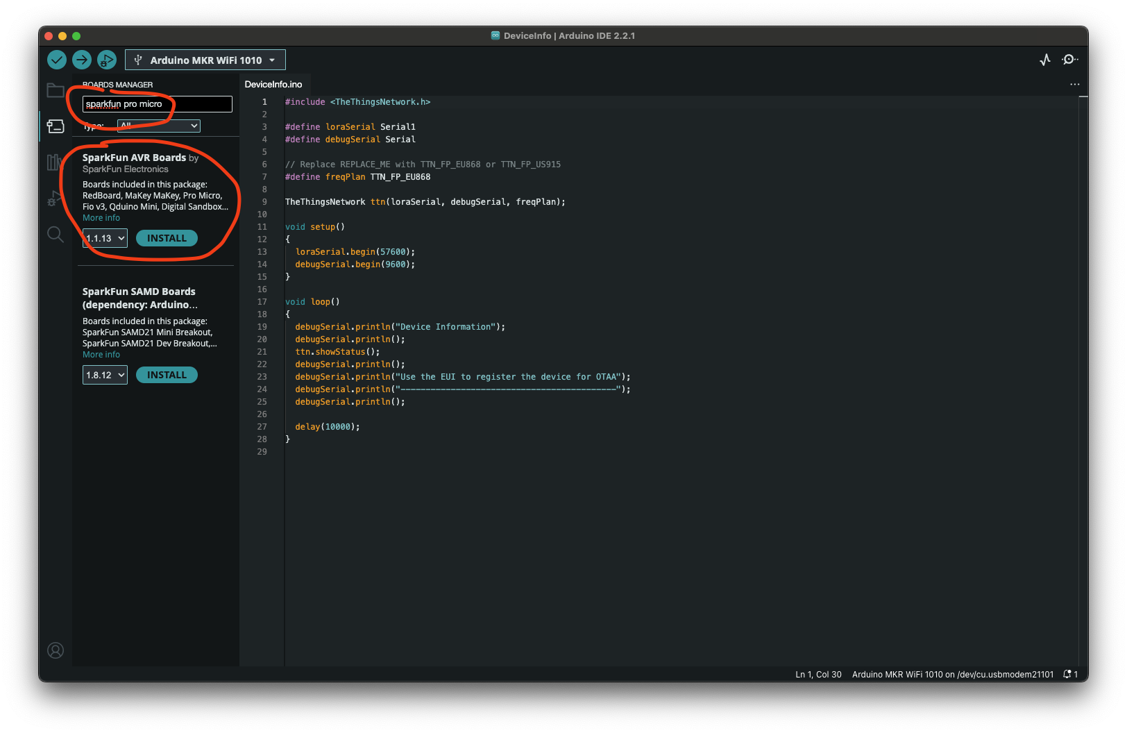
In the Arduino IDE, select Tools > Boards > SparkFun Pro Micro
Select Tools > Processor > ATmega32U4 (3.3V, 8Mhz)
Select the Node's Serial Port under Tools > Port
Upload the sketch using the Upload button
Open the Serial Monitor:Tools -> Serial Monitor
and copy the DevEUI value as shown below:
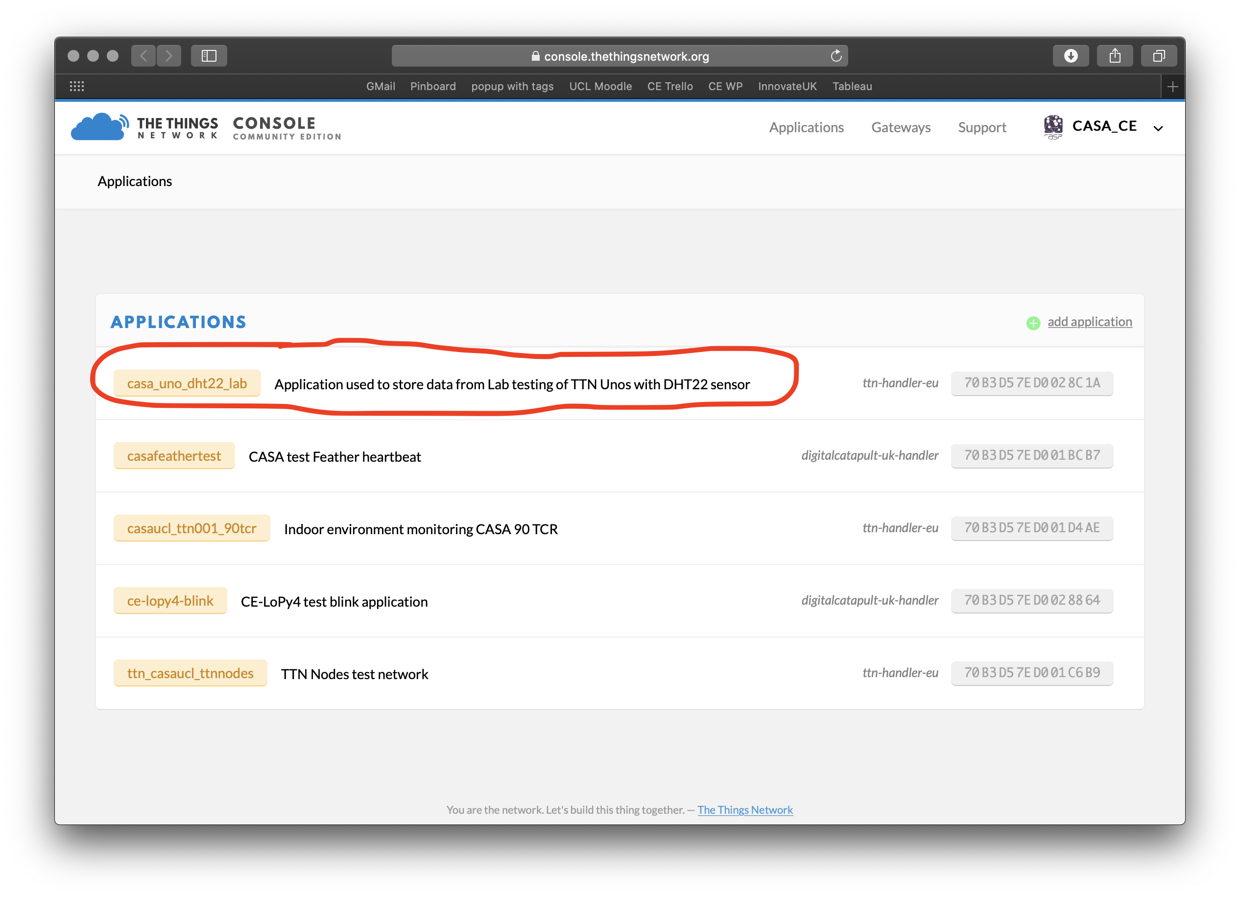
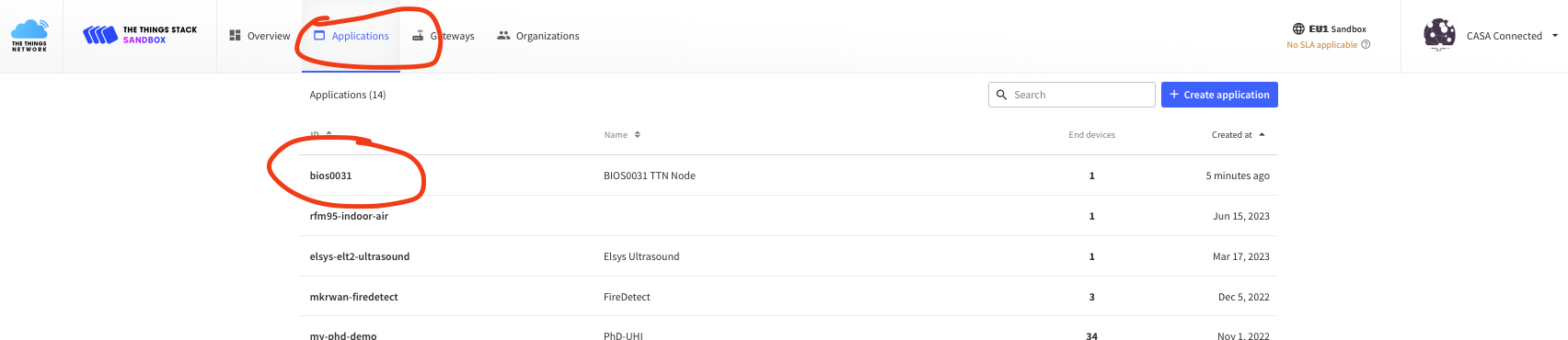
Open a browser and navigate to the the Application for this workshop on the Things Network
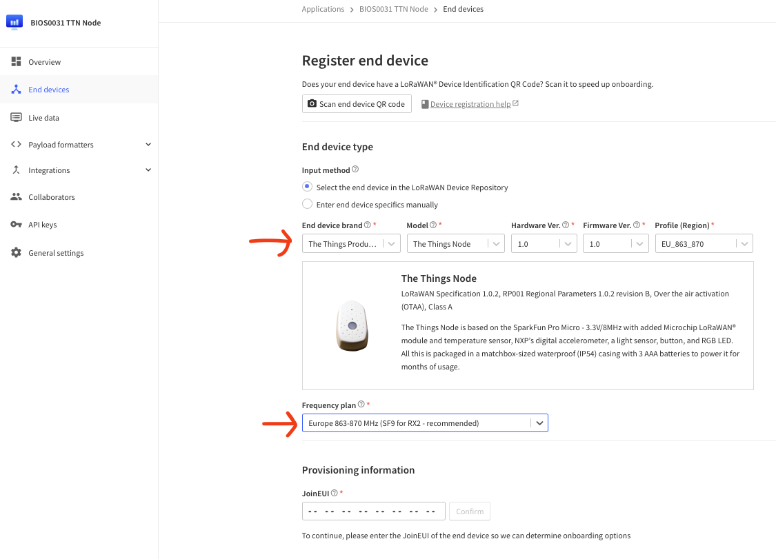
In the Devices section click on ‘register device'. You should see a window simialar to below once you start filling out the drop down menus.
In the JoinEUI box enter all 0's (0000000000000000)
In the ‘Device EUI' box paste the value of the DevEUI from the previous section.
Finally, click on the Register button at the bottom right of your screen.
Positive
! Your device is now registered with the application!
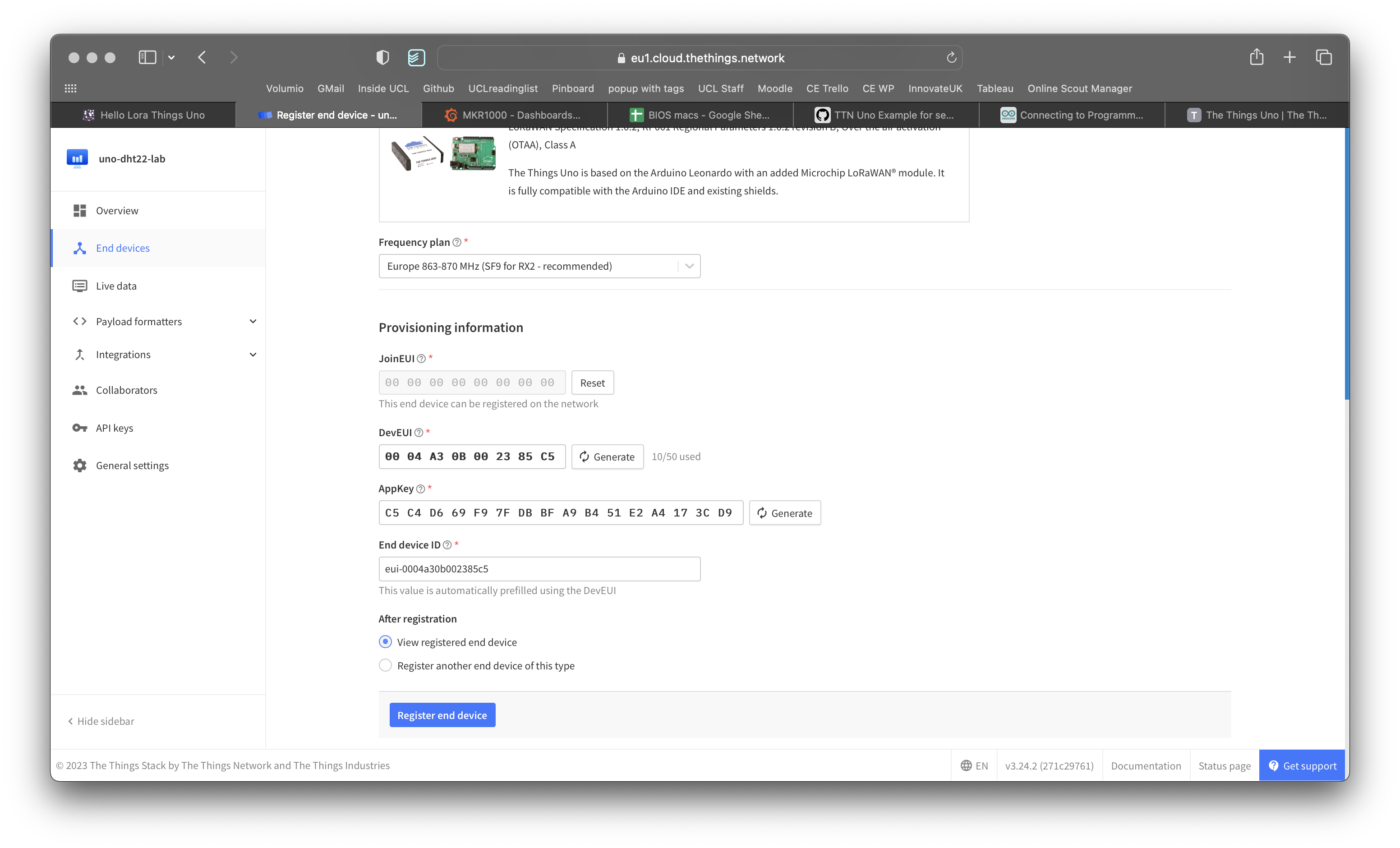
Open a browser and navigate to the the Application for this workshop on the Things Network
In the Devices section click on ‘register device'. You should see a window simialar to below once you start filling out the drop down menus.
In the JoinEUI box enter all 0's (0000000000000000)
In the ‘Device EUI' box paste the value of the DevEUI from the previous section.
Click generate on the AppKey and copy the value of the AppKey since you will use that later when registering your device.
Add your UCL username to the start of the End Device ID (to make it easier to find amongst the 50 others that will be generated!)
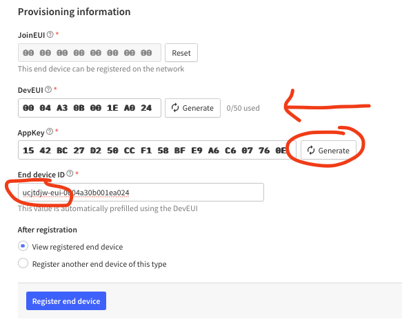
Finally, click on the Register button at the bottom right of your screen.
Positive
! Your device is now registered with the application!
Return to the Arduino IDE and open this Arduino sketch from GIST
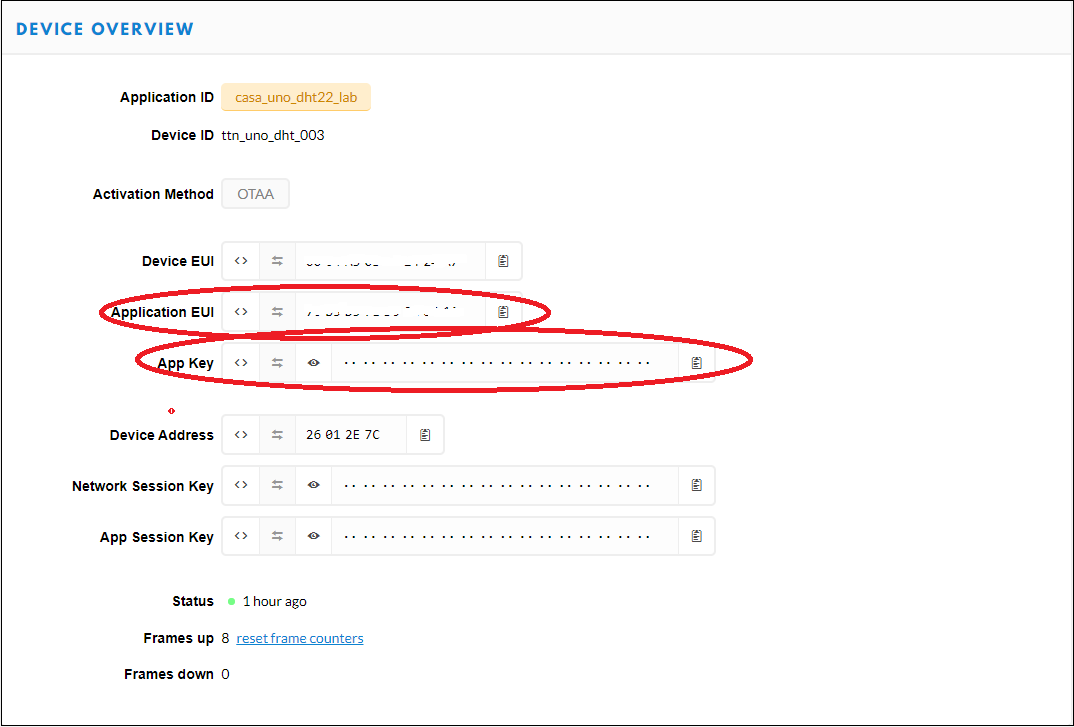
Update the code below with your values. You will need to replace <APP_EUI> with the actual value of your Application_EUI copied from the Things Network console Device Overview (see below). Similarly, replace <APP_KEY> with the actual value of your App Key obtained from the Things Network console Device Overview.
// Set your AppEUI and AppKey
const char *appEui = "<APP_EUI>";
const char *appKey = "<APP_KEY>";
(Hint: scroll to bottom of Device Information page if you prefer to copy paste...)
Find the line #define debugSerial Serial1 below it we have defined another serial connection for the Lora communication interface (Note, the ‘other' Serial connection is to your terminal so that you can see debug data):
#define loraSerial Serial1
Immediately below this your region is set to be EU:
#define freqPlan TTN_FP_EU868
The following line creates a constructor to setup a TTN object:
TheThingsNetwork ttn(loraSerial, debugSerial, freqPlan);
In the setup() code we start both serial interfaces:
  loraSerial.begin(57600);
  debugSerial.begin(9600);
We establish a connection to the Lora Gateway:
  ttn.showStatus();
  debugSerial.println("-- JOIN");
  ttn.join(appEui, appKey);
To minimise the size of the payload transmitted over LoRa, it is necessary to convert our sensor values to unsigned integers. To avoid loosing precision we multiply the sensor values by 100 (applying the reverse transformation at the Things Network backend).
In the loop() code you should see:
// converting that reading to voltage, for 5.0v arduino use 5.0
int reading = analogRead(sensorPin);
float voltage = reading * 5.0;
voltage /= 1024.0;

//converting from 10 mv per degree wit 500 mV offset
//to degrees ((voltage - 500mV) times 100)
float tempC = (voltage - 0.5) * 100 ;

// Read sensor values and multiply by 100 to effictively have 2 decimals
uint16_t temperature = tempC * 100;
Next we convert our sensor values to binary and upload them to the ThingsNetwork (note we are only using 2 bytes of a potential 8 byte payload here):
  // Split both words (16 bits) into 2 bytes of 8
  byte payload[2];
  payload[0] = highByte(temperature);
  payload[1] = lowByte(temperature);
Finally we upload the data to the Things Network as shown below
ttn.sendBytes(payload, sizeof(payload));
Your sketch should now look like this:
/*
 Circuit:
 * TMP36 middle pin attached to pin A0, left to VCC, right to GND
 created Feb 2023
 by Duncan Wilson
 */
#include <TheThingsNetwork.h>

// Set your AppEUI and AppKey
const char *appEui = "xxx";
const char *appKey = "xxx";

#define loraSerial Serial1
#define debugSerial Serial

// Replace REPLACE_ME with TTN_FP_EU868 or TTN_FP_US915
#define freqPlan TTN_FP_EU868
TheThingsNetwork ttn(loraSerial, debugSerial, freqPlan);

//TMP36 Pin Variables
int sensorPin = A0; //the analog pin the TMP36's Vout (sense)

void setup()
{
  loraSerial.begin(57600);
  debugSerial.begin(9600);

  // Wait a maximum of 10s for Serial Monitor
  while (!debugSerial && millis() < 10000)
    ;

  debugSerial.println("-- STATUS");
  ttn.showStatus();

  debugSerial.println("-- JOIN");
  ttn.join(appEui, appKey);

}

void loop()
{
  debugSerial.println("-- LOOP");

  // converting that reading to voltage, for 5.0v arduino use 5.0
  int reading = analogRead(sensorPin);
  float voltage = reading * 5.0;
  voltage /= 1024.0;

  //converting from 10 mv per degree wit 500 mV offset
  //to degrees ((voltage - 500mV) times 100)
  float tempC = (voltage - 0.5) * 100 ;

  // Read sensor values and multiply by 100 to effictively have 2 decimals
  uint16_t temperature = tempC * 100;

  // Split both words (16 bits) into 2 bytes of 8
  byte payload[2];
  payload[0] = highByte(temperature);
  payload[1] = lowByte(temperature);

  debugSerial.print("Temperature: ");
  debugSerial.println(temperature);

  ttn.sendBytes(payload, sizeof(payload));

  delay(60000); // wait a minute
}
Compile the code and once you have the code compiling sucessfully you can upload the sketch to the Things Uno board.
Save the sketch.
Now return to the Things Network console for your device and open the Data tab (see below):
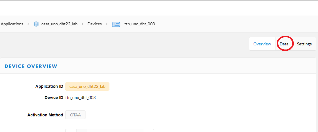
You should be able to see the data uploaded by your device.
To dig a little deeper into how messages can be sent to and from the Things Uno take a look at the quick start guide on TTN
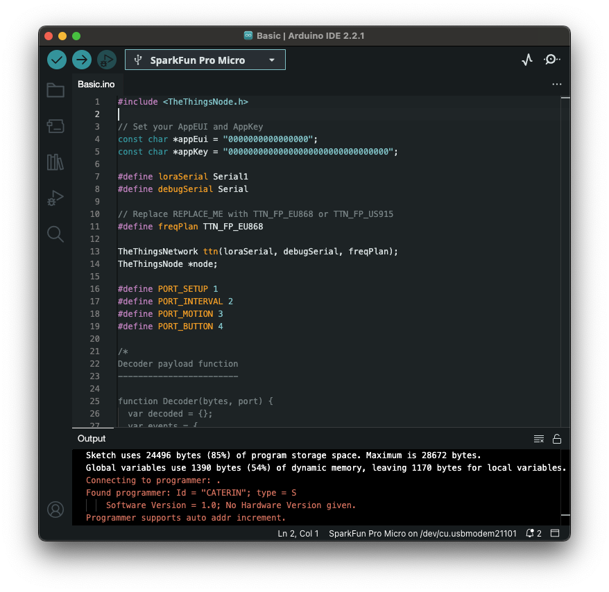
Return to the Arduino IDE and open a demo script from the examples folder:
File > Examples > TheThingsNode > Basic
Update the code below with your values. You will need to replace <APP_EUI> with the actual value of your Application_EUI copied from the Things Network console Device Overview (note in our case we assigned 0000000000000000 as our appEUI - which is fine for demo or research projects - commercial products will sometimes have an appEUI for simplifying remote management). Similarly, replace <APP_KEY> with the actual value of your App Key obtained from the Things Network console Device Overview (hopefully you copied this down somewhere in the previous step - if not you can look it up on the Things Network webpage for the device that you just created).
// Set your AppEUI and AppKey
const char *appEui = "<APP_EUI>";
const char *appKey = "<APP_KEY>";
(Hint: scroll to bottom of Device Information page if you prefer to copy paste...)
The only other variable we need to edit is the freqPlan set this to your region (it might already be EU by default):
#define freqPlan TTN_FP_EU868
Compile the code and upload the sketch to the Things Node.
If you are wanting to learn about what is going on in the program the outline below provides a quick run through of the code:
In the first block below we:
- include the thingsnode code library (which allows us to use commands like
TheThingsNode) - declare some global variables (appEui and appKey)
- define some variables for freqPlan and the sensors on the device
- creates a constructor to setup an object type TheThingsNetwork called
ttnwhich we use to connect to a Lora Gateway - creates a constructor to setup an object of type TheThingsNode called
nodewhich will allow us to access things like sensor values
#include <TheThingsNode.h>

// Set your AppEUI and AppKey
const char *appEui = "0000000000000000";
const char *appKey = "00000000000000000000000000000000";

#define loraSerial Serial1
#define debugSerial Serial

// Replace REPLACE_ME with TTN_FP_EU868 or TTN_FP_US915
#define freqPlan TTN_FP_EU868

TheThingsNetwork ttn(loraSerial, debugSerial, freqPlan);
TheThingsNode *node;

#define PORT_SETUP 1
#define PORT_INTERVAL 2
#define PORT_MOTION 3
#define PORT_BUTTON 4
The next bit of code is all commented out but includes sample code for the payload decoder on TTN - more on that later in the final tab.
/*
Decoder payload function
------------------------

function Decoder(bytes, port) {
  var decoded = {};
  var events = {
    1: 'setup',
    2: 'interval',
    3: 'motion',
    4: 'button'
  };
  decoded.event = events[port];
  decoded.battery = (bytes[0] << 8) + bytes[1];
  decoded.light = (bytes[2] << 8) + bytes[3];
  if (bytes[4] & 0x80)
    decoded.temperature = ((0xffff << 16) + (bytes[4] << 8) + bytes[5]) / 100;
  else
    decoded.temperature = ((bytes[4] << 8) + bytes[5]) / 100;
  return decoded;
}
*/
The setup function is quite long but it does the following:
- creates another serial connection for the Lora communication interface
loraSerial(Note, the ‘other' Serial connectiondebugSerialis your serail monitor - "the USB cable" so that you can see debug data via theprintandprintlncommands). - the while loop is called to wait for a serial connection to be established so that things printed to screen can be displayed and are not missed
- the config node section does just that using functions from TheThingsNode library, it defines the sensor functions you want to use in the sketch
- the next two lines call the showStatus and setColor functions (if the light goes green it means the preceding step
showStatusexecuted ok and the board is ready for a connection to Gateway) - the next three code blocks print the status to the serial monitor, call the
ttn.joinfunction to create a connection to the things network and finally sends some dataPORT_SETUPto register the device on the network
void setup()
{
  loraSerial.begin(57600);
  debugSerial.begin(9600);

  // Wait a maximum of 10s for Serial Monitor
  while (!debugSerial && millis() < 10000)
    ;

  // Config Node
  node = TheThingsNode::setup();
  node->configLight(true);
  node->configInterval(true, 60000);
  node->configTemperature(true);
  node->onWake(wake);
  node->onInterval(interval);
  node->onSleep(sleep);
  node->onMotionStart(onMotionStart);
  node->onButtonRelease(onButtonRelease);

  // Test sensors and set LED to GREEN if it works
  node->showStatus();
  node->setColor(TTN_GREEN);

  debugSerial.println("-- TTN: STATUS");
  ttn.showStatus();

  debugSerial.println("-- TTN: JOIN");
  ttn.join(appEui, appKey);

  debugSerial.println("-- SEND: SETUP");
  sendData(PORT_SETUP);
}
The actual loop of the program is really simple, it just calls a function within the node library called loop. If you were to look in the code of the library Arduino > libraries > TheThingsNode > src > TheThingsNode.cpp amongst the hundreds of lines of code you would see a function called loop defined (about line 100 i think).
void loop()
{
  node->loop();
}
The functions below are hopefully reasonably self explanatory - they define what happens when the following events happen:
- interval - when this runs data is sent to the gateway (ie led lights blue)
- wake - coming out of energy saving mode
- sleep - going into energy saving mode so turns off LED
- onMotionStart - device contains accelerometer so sends data when moved
- onButtonRelease - what happens when button is pressed
For more information on the events available in the library you can take a look at the API documentation
void interval()
{
  node->setColor(TTN_BLUE);

  debugSerial.println("-- SEND: INTERVAL");
  sendData(PORT_INTERVAL);
}

void wake()
{
  node->setColor(TTN_GREEN);
}

void sleep()
{
  node->setColor(TTN_BLACK);
}

void onMotionStart()
{
  node->setColor(TTN_BLUE);

  debugSerial.print("-- SEND: MOTION");
  sendData(PORT_MOTION);
}

void onButtonRelease(unsigned long duration)
{
  node->setColor(TTN_BLUE);

  debugSerial.print("-- SEND: BUTTON");
  debugSerial.println(duration);

  sendData(PORT_BUTTON);
}
The last block of code is called sendData which is where much of the magic happens! Each time the function is called it:
- wakes the device
- prints some status info to serial monitor using built in functions in the library
- creates a
bytespayload to hold the sensor data we want to send - sends the bytes as a
payload - send device to sleep for 60,000 milliseconds (1 minute)
The byte structure of the payload is the one of the more challenging concepts to get your head around. Some really nice explanation is on the TTN site
void sendData(uint8_t port)
{
  // Wake RN2483
  ttn.wake();

  ttn.showStatus();
  node->showStatus();

  byte *bytes;
  byte payload[6];

  uint16_t battery = node->getBattery();
  bytes = (byte *)&battery;
  payload[0] = bytes[1];
  payload[1] = bytes[0];

  uint16_t light = node->getLight();
  bytes = (byte *)&light;
  payload[2] = bytes[1];
  payload[3] = bytes[0];

  int16_t temperature = round(node->getTemperatureAsFloat() * 100);
  bytes = (byte *)&temperature;
  payload[4] = bytes[1];
  payload[5] = bytes[0];

  ttn.sendBytes(payload, sizeof(payload), port);

  // Set RN2483 to sleep mode
  ttn.sleep(60000);

  // This one is not optionnal, remove it
  // and say bye bye to RN2983 sleep mode
  delay(50);
}
If you got this far - awesome! Hopefully the code makes sense. The Getting started page is also worth talking a look if you want to dig a little deeper.
In the next page we will see where this transmitted data ends up and how we process it.
Now return to the Things Network console for your device and open the Data tab (see below):
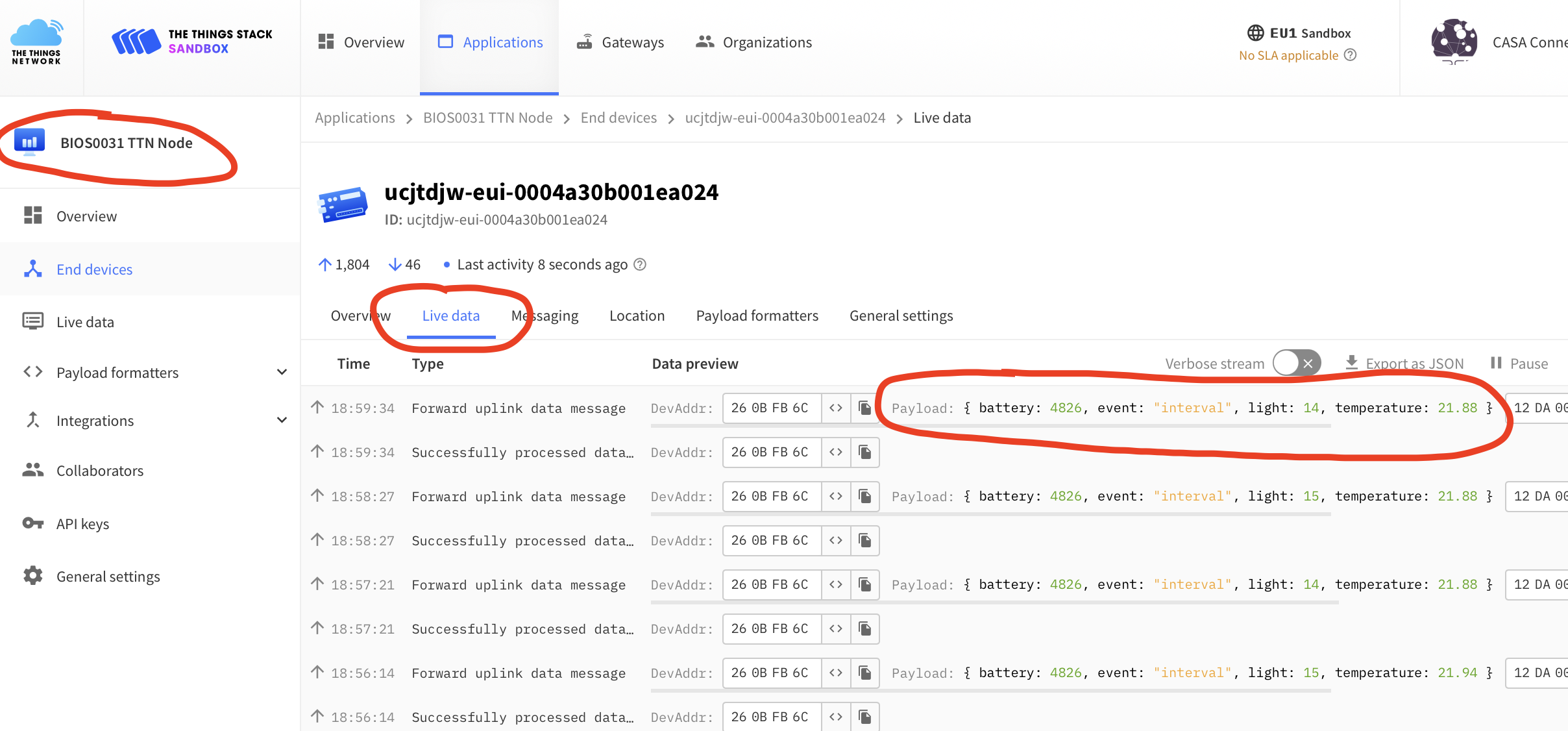
You should be able to see the data uploaded by your device.
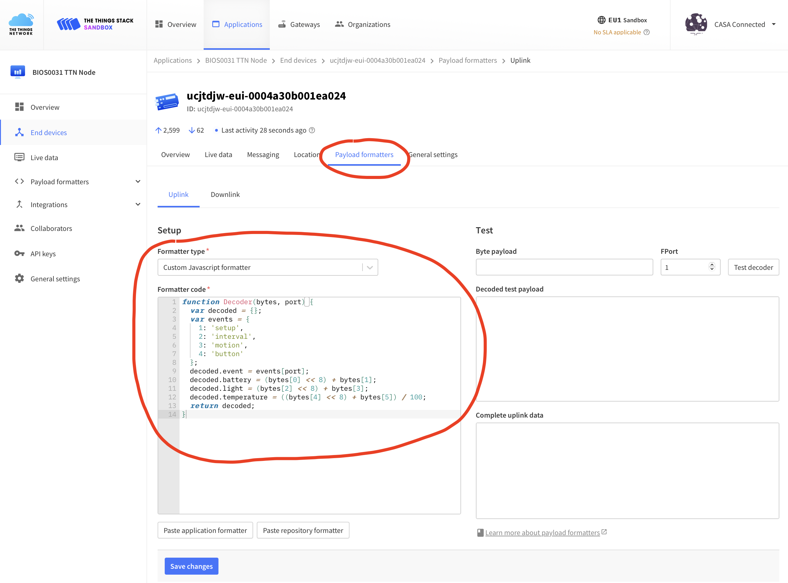
For this application we are using an application wide Payload Decoder due to the nature of this being a tutorial and I know that all devices connecting to the application do so in the same way (ie with the same payload structure). To minimise the amount of data sent over the network we package it up in a minimal format (the byte payload in the previous Arduino sketch). As an example, included below is a payload decoder for a ThingsNode (one of the two boards used in this tutorial). If you click on the Payload formatters tab you will see the decoding code that was commented in the ThingsNode Arduino sketch.
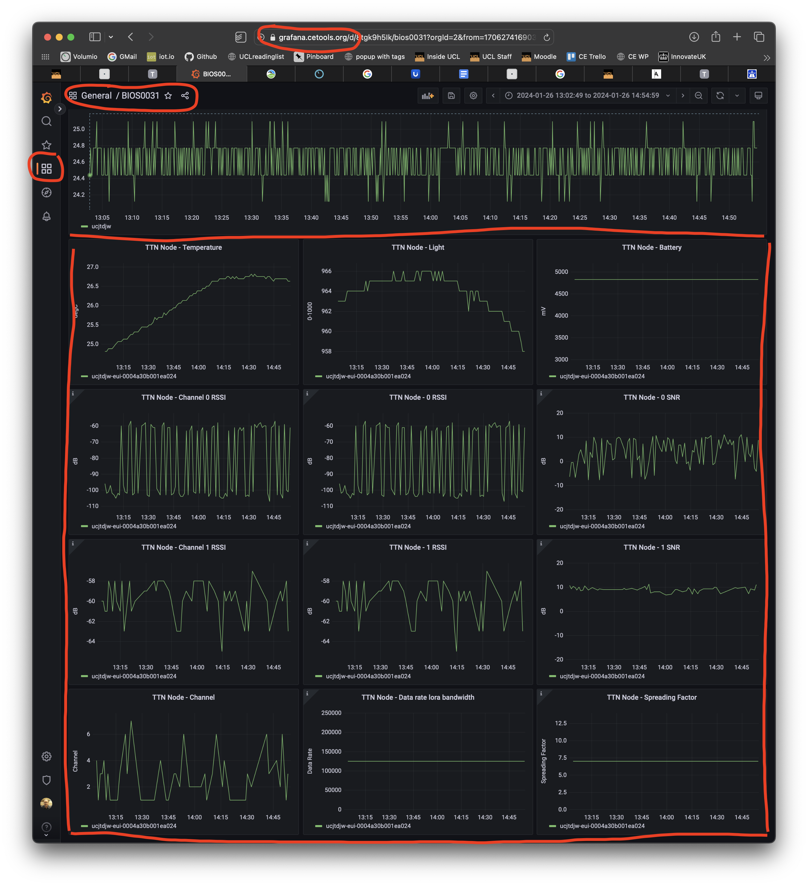
We have also created a Grafana Dashboard (select the browse dashboards - four squares - and then select BIOS0031)
The End.